{domain:"www.qualitydigest.com",server:"169.47.211.87"} Skip to main content

        
User account menu
Main navigation
  • Topics
    • Customer Care
    • Regulated Industries
    • Research & Tech
    • Quality Improvement Tools
    • People Management
    • Metrology
    • Manufacturing
    • Roadshow
    • QMS & Standards
    • Statistical Methods
    • Resource Management
  • Videos/Webinars
    • All videos
    • Product Demos
    • Webinars
  • Advertise
    • Advertise
    • Submit B2B Press Release
    • Write for us
  • Metrology Hub
  • Training
  • Subscribe
  • Log in
Mobile Menu
  • Home
  • Topics
    • Customer Care
    • Regulated Industries
    • Research & Tech
    • Quality Improvement Tools
    • People Management
    • Metrology
    • Manufacturing
    • Roadshow
    • QMS & Standards
    • Statistical Methods
    • Supply Chain
    • Resource Management
  • Login / Subscribe
  • More...
    • All Features
    • All News
    • All Videos
    • Training

Why Faster Scanners Don’t Always Mean Faster Inspection

User error, bottlenecks, and other factors contribute to delays

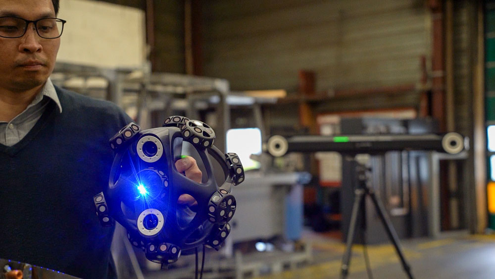
Hyperscan. Image Credit: Hexagon

Darren Goh
Bio

Hexagon

Thu, 08/06/2026 - 12:03
  • Comment
  • RSS

Social Sharing block

  • Print
Body

Ask anyone who’s bought a handheld 3D scanner with optical tracking system in the last few years about what sold them, and you’ll hear about speed. More points per second. Larger scanning areas. Faster data capture.

ADVERTISEMENT

Those improvements matter. But when you look at the entire inspection process, from the moment a part arrives for measurement to the moment a report is delivered, the scanner itself is often no longer the bottleneck.

The bottleneck is everything that happens around the scan.

It’s establishing alignments before measurement can begin. It’s switching to a different device to capture features the scanner can’t see. It’s refixturing parts because probing and scanning systems operate in separate coordinate frames. It’s exporting, importing, and realigning data because two tools that should work together were never designed to.

Each of these costs just a few minutes on their own, but when you stack them on an inspection plan with dozens of features, across a shift or across a week, those “gaps” add up to more lost time than the scanning ever consumed.

That’s the part the spec sheet doesn’t tell you. And it’s why the productivity conversation in dimensional measurement is changing. Speed delivered significant gains during the last decade. The next gains will come from reducing friction throughout the workflow, not simply accelerating a single step within it.

Two things optical scanning can’t always do on its own

The limitations of optical scanning help explain where workflow inefficiencies often emerge.

A laser scanner measures the surfaces it can see. That’s its job, and modern scanners do it beautifully.

But some features remain difficult or impossible to capture reliably with optical scanning alone. Deep bores, enclosed cavities, and hidden mating surfaces are often critical inspection points, yet they might fall outside the scanner’s line of sight. In those situations, contact measurement is often the most practical solution.

The second limit is alignment. Before you scan anything useful, you usually establish a coordinate system: a datum plane, a couple of reference circles, a line. You can do this by scanning surfaces and fitting geometry to them. But for primary datums, a touch probe is often faster and more deterministic. Probe three points, you have a plane. Probe a bore, you have a circle. It’s quick, repeatable, and familiar to many inspectors.

So in practice, real inspection is a mix: Probe to set up the part, scan the surfaces, probe the features the laser can’t reach.

The challenge is that, historically, combining probing and scanning often meant working across two different systems and switching between them throughout the inspection process.

The hidden tax of switching tools

Here’s where the productivity drain becomes visible once you look for it.

If your scanner does scanning, and a separate device does probing, you’re not running one workflow. You’re running two, bolted together. Two coordinate systems that must be reconciled. Two software environments to learn and license. And every time you move from one to the other, you pay an alignment tax—reestablishing the relationship between probe data and scan data so they can be analyzed as a single measurement.

None of these steps is dramatic on its own. That’s precisely why they often go unnoticed. But over dozens of inspections and hundreds of parts, the accumulated time can become substantial.

Measuring in one coordinate system

The fix isn’t a faster scanner. It’s removing the handoffs.

What changes when contact probing lives inside the same tracked coordinate system as the scanner is that the switching tax disappears. You probe to set your datum. You scan the surface. You probe the hidden point. Everything is referenced to one coordinate frame, captured in one session, with no refixturing and no offline realignment in between. The inspector stops thinking about which device owns which task and just measures the part.

This thinking is behind HYPERPROBE, which extends the HYPERSCAN system with wireless contact probing. Rather than introducing another stand-alone workflow, it adds contact measurement capability within the same tracked environment used for scanning.

Because the same camera bar that tracks the scanner also tracks the probe, both feed the same coordinate system. Probe accuracy is specified down to 0.05 mm, with overall volumetric performance inherited from the host scanner. You probe and you scan, in one coordinate, with one software package.

What does that actually look like on the floor?

Fixture setup: Probe the fixture with live feedback as you go so you can adjust and confirm the build in real time instead of scanning, exporting, checking, and walking back.

Castings: Capture the hidden points inside a cavity that the scanner has no line of sight to, then scan the visible surfaces, all in the same reference frame.

Fuel tanks and enclosed assemblies: Measure internal features that are inaccessible to optical scanning while maintaining a common coordinate reference.

Aerospace mold alignment: Establish datums through probing, verify alignment in real time, and complete scanning within the same measurement environment.

There’s a quieter benefit, too. Because the tracking system follows both the probe and the part independently, the part doesn’t have to be locked down to be measured. It can move and the measurement holds. For anyone who’s tried to clamp an awkward component perfectly still just so two separate systems agree on where it is, that’s not a small thing.

What this means for how you evaluate a system

If there’s a single practical takeaway, it’s this: When you assess measurement productivity, evaluate the workflow, not just the scan speed.

Counting points per second tells you how quickly one step runs. It doesn’t account for the time spent switching devices, changing software, refixturing parts, or realigning data. Before comparing systems based on scan speed alone, map the full inspection workflow. Those transitions are often where the greatest productivity opportunities exist.

Faster scanning was the right priority for many years, and hardware performance has improved dramatically. But parts have become more complex, tolerances have tightened, and skilled inspection resources remain limited. Increasing capacity today is less about capturing data faster and more about eliminating unnecessary workflow steps.

For many manufacturers, the next productivity gains will come from reducing handoffs, minimizing workflow interruptions, and creating a more continuous path from measurement to decision. In that sense, inspection efficiency is becoming less about scan speed and more about workflow continuity.

Add new comment

The content of this field is kept private and will not be shown publicly.
About text formats
Image CAPTCHA
Enter the characters shown in the image.

© 2026 Quality Digest. Copyright on content held by Quality Digest or by individual authors. Contact Quality Digest for reprint information.
“Quality Digest" is a trademark owned by Quality Circle Institute Inc.

footer
  • Home
  • Print QD: 1995-2008
  • Print QD: 2008-2009
  • Videos
  • Privacy Policy
  • Write for us
footer second menu
  • Subscribe to Quality Digest
  • About Us