Precision Micro
Social Sharing block
Researchers at the Karlsruhe Institute of Technology recently found that manufacturing process selection influences product design outcomes, yet is still often guided by experience rather than structured evaluation of alternatives. Understanding the differences between chemical etching and other metal-shaping methods is essential to making more informed process selection decisions.
|
ADVERTISEMENT |
Different metal-shaping methods remove material in different ways. Mechanical processes use force, thermal methods use heat, and chemical etching uses controlled chemical reactions. These differences directly affect material integrity and reliability. You can model the perfect geometry in computer-aided design (CAD), but the way you cut or form it can change what the surface and near-surface layer actually looks like and how it performs.
Here, we’re focusing on commonly used sheet metals and engineering alloys (0.01–2.5 mm thickness), including steels, stainless steels, nickel and nickel alloys, copper and copper alloys, aluminum, and similar materials. Each process has practical limits in terms of thickness, material, and achievable features, factors that must be considered during process selection.
These considerations are particularly relevant as reviews of machining “surface integrity” show that material removal processes can alter microstructure, introduce residual stress, and create surface anomalies, making it important to assess manufacturing options carefully.
Mechanical methods
Let’s start with mechanical processes. Stamping, punching, and CNC machining remain widely used because of their scalability. Once tooling is established, they can produce large volumes of consistent components quickly and cost effectively.
This is why they are widely used in automotive and electronics. However, these processes rely on physical force to cut, form, or remove material, and that interaction inevitably affects the metal itself.
When a punch or cutting tool shears material, it plastically deforms. This is a permanent altering of the material structure, usually affecting the surrounding region, where it produces burrs, edge deformation, and localized strain.
In fact, surface integrity studies show that machining and shearing processes introduce mechanical and thermal loads that can alter subsurface material properties and introduce residual stress, which may affect fatigue performance and long-term reliability.
These effects usually require additional finishing operations like deburring, grinding, or polishing to meet functional requirements. Burr formation is a recognized and largely unavoidable outcome of machining. Research in light metal alloy applications highlights that deburring is a necessary but nonvalue-adding process that can significantly increase production effort and cost.
Residual stress is another consideration. The U.K. National Physical Laboratory (NPL) confirms that machining and forming processes introduce internal stresses that can lead to distortion, reduced fatigue life, and dimensional instability, particularly in precision components.
In addition, mechanical processes can impose practical limits on achievable geometry. Producing very fine features, sharp internal corners, or thin, delicate structures may require specialized tooling or secondary machining operations.
Tool wear further complicates production over time, affecting dimensional accuracy and process consistency. The aforementioned research also highlights that tool wear influences machining performance, especially in precision applications requiring tight tolerances.
Thermal shaping
Another approach to shaping metal is thermal processing. Instead of physically cutting or deforming the material, these methods use concentrated energy. This is typically in the form of a laser, plasma arc, or electrical discharge to melt or vaporize material along a defined path. This allows engineers to produce intricate geometries, fine features, and complex internal profiles that would be difficult or impractical using conventional mechanical tooling.
Because thermal processes don’t rely on physical cutting forces, they avoid many of the deformation effects associated with punching or machining. However, the introduction of heat creates its own set of material considerations.
When a laser or electrical discharge interacts with a metal surface, it generates a highly localized thermal cycle. This produces what is known as a heat-affected zone (HAZ), a region where the material has been exposed to elevated temperatures and undergoes microstructural changes, even though it doesn’t melt.
These microstructural changes can directly influence mechanical performance. A 2021 survey of existing research found that heat-affected zones can significantly reduce material strength in certain alloys. This includes reductions of up to 50% in aluminum alloys, and proof stress reductions of up to 70%, depending on material condition and thermal exposure.
The NPL also found that residual stresses generated during machining can reach extremely high levels, typically around 500 MPa and up to several gigapascals in hard materials. These are levels that are more than sufficient to influence flexural strength and long-term component performance.
What’s more, thermal cutting processes can produce recast layers. These are thin layers of resolidified material that form when molten metal cools rapidly at the cut surface.
Such altered surface layers often differ in microstructure and mechanical properties from the original base material, which may require secondary finishing processes to restore optimal surface integrity.
Chemical machining
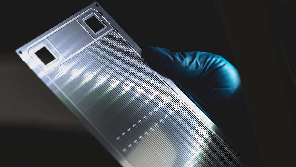
An alternative option is chemical etching, also known as photochemical machining (PCM). Unlike mechanical or thermal processes, this method removes material through controlled chemical reactions rather than force or heat.
A photoresist mask defines the component geometry, and the exposed metal is selectively dissolved using etchants. Because material is removed chemically, PCM avoids the deformation and thermal effects associated with conventional shaping methods.
A step-by-step illustration of the chemical etching process. Credit: Precision Micro
A recent manufacturing review revealed that PCM is a stress-free process that doesn’t introduce residual stress, burrs, or deformation. Neither does it alter hardness, grain structure, or ductility, because no cutting forces or thermal loads are applied.
Research published in the 2025 Journal of Tribology also suggests that photochemical machining is a viable option for producing microstructures and precision components. This is while maintaining material integrity and avoiding the stress and deformation associated with conventional manufacturing methods.
Another advantage is tooling flexibility. Chemical etching uses phototools, rather than hard tooling like dies or punches, that can be created quickly and modified easily for faster design iterations and lower tooling costs. Because phototools don’t have mechanical wear, they also maintain accuracy throughout production.
From an engineering perspective, this supports faster product development and enables manufacturers to adapt quickly to changing design requirements. However, just as all additive or subtractive processes have practical limitations, chemical etching is best suited to sheet metals that are relatively thin. Typical ranges include steels and stainless steels (0.01–2.5 mm), nickel, copper, aluminum, and similar engineering alloys (0.01–1.5 mm). Thicker metals are often less economical to process due to etch time and chemical requirements. Sheet dimensions also vary depending on the process and material. But the method is most effective for plates up to about 600 mm × 1,500 mm.
However, chemical etching still works for a wide variety of commonly used metals and alloys. These include low-carbon and high-carbon steels, maraging steels, and electrical steels. It’s also suitable for stainless steels, including austenitic, ferritic/martensitic, precipitation-hardened, duplex, and super duplex grades.
Nickel alloys such as Inconel, Monel, and Invar can likewise be processed, along with copper and copper alloys including beryllium copper, brass, and phosphor bronze. Aluminum and aluminum bronzes are compatible, too, as are other specialty metals such as molybdenum or metalized polyimide films.
As with any manufacturing process, understanding these material and thickness constraints is essential to selecting the right shaping method for the component’s design and application. However, the flexibility that chemical etching offers enables engineers to produce fine features, delicate geometries, and complex patterns that might be challenging with mechanical or thermal methods, while preserving material integrity.
Mechanical shaping introduces force, thermal shaping introduces heat, and both can affect material integrity. Meanwhile, chemical etching removes material without introducing either, allowing engineers to preserve material properties while achieving precise geometries.
Understanding these differences helps to inform process selection decisions, ensuring that manufacturing supports, rather than compromises, design intent. That’s why design outcomes should be guided by a structured evaluation of alternatives as opposed to experience.
For more information on chemical etching, download Precision Micro’s latest white paper here.
Add new comment