Jeff Bibee  |  03/31/2009

Understanding Optical Measurement

All systems are not created equal.

Optical measurement, when clearly understood and applied, can bring huge benefits. It can also be an investment disaster. To avoid the latter, we need to start with an understanding of the basics--the capabilities and limitations of optical measurement. Then, we can consider the applications where it might provide a better solution over current methods, such as touch probes, optical comparators, hand gauges, or microscopes. Digging deeper, we can discover the challenges that those applications present to optical measurement, the limitations, and the potentials for failure. In this article, we will investigate the optical tools and software strategies that have been developed to meet those challenges. With a deeper understanding, the right technology can be applied to the task, and the investment dollars will make sense.

The basics

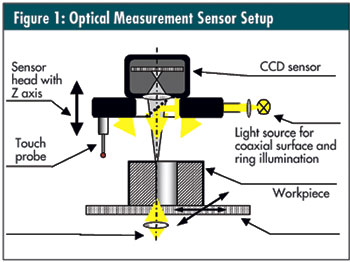
The diagram in figure 1 below illustrates the basics of optical measurement: lighting, optics, XY Stage, and a Z axis that handles the focus.

Lighting is used to illuminate the workpiece or object to be measured. There are three basic lighting schemes. Backlight is used to light the part in silhouette to measure outer profiles and features such as through holes. Direct lighting is integrated into the optical beam path and lights the part from a direct vertical angle. A ring light is a light source that is mounted around the optics and illuminates the workpiece at indirect angles.

The optical sensor has a set of lenses through which the reflected light (or direct light in the case of backlighting) passes. The light is focused on a camera that contains an optical chip, or CCD. The CCD has a pixel array that is light-sensitive. The chip converts the light-intensity value for each pixel into an electronic signal with a corresponding value for each pixel. This is called a “gray-scale value” and is a number between 0 and 255. The software finds an edge by determining where the gray-scale value between two neighboring pixels drastically changes. The software takes the positions of these edges on the optical sensor and compiles that with the XYZ position of the measuring machine to provide the coordinate locations. An edge-finder system links a few of these boundary points together to create edges or contours of the part features.

Measurements are made in the Z axis using the contrast or “autofocus” method. An automatic cycle will move the Z axis of the machine and thus the focal point of the optics through the surface of the part. Numerous images are taken and evaluated for contrast. The image has the best contrast when it is exactly in the focal plane. By selecting the image with the best contrast and knowing the Z position of the axis for that image and the calibrated focal point distance of the optics, the height of the part at any XY position can be calculated.

Advantages

The significant difference between optical measurement and touch-probe measurement is that the touch-probe method finds the edges of parts by calculating the intersection of planes and other features based on a few points. Optics can find the edges directly. Touch-probe systems are limited in their analysis by the amount of points that they gather. Further, each point eats away at precious measurement cycle time because each measurement requires that the probe approach, contact, withdraw, and reposition. Optics can gather hundreds of points with each snapshot. Any feature that can be measured optically can be measured faster and more accurately due to the amount of information quickly gathered. Programming time for machine positioning is also shortened.

The advantages of optical measurement over optical comparators, hand gauges, microscopes, and other operator- dependent methods seem obvious. An automated system, properly applied, can gain control of cycle time, provide the data for statistical analysis and real-time control, and eliminate operator influence on the data. The key word here is automated.

Disadvantages

Obviously, there are certain feature characteristics that optics cannot measure. Cylindricality and tapers in bores cannot be measured optically. Perpendicularity of vertical faces to horizontal faces cannot be measured without additional costs of rotary axes or right-angle optics. Thus, the advent and prominence of the multisensor coordinate measuring machine (MS-CMM).

One disadvantage of automated optical measurement, or CMM measurement in general, vs. manual methods can be cycle time. If only a few dimensions are required, it may be faster to simply take them manually. Automated measurements take some setup time for part alignment before any measurement can occur. This can often be overcome with creative programming or multipart fixturing.

Another concern is the “judgment call.” The human eye-brain connection is a powerful, even if inaccurate, system. With optical comparators, a person can filter out burrs and debris as he or she eyeballs a dimension with a crosshair. A person can ensure that the correct contour is selected. The software system behind the optical sensor should be, but isn’t always, equally capable.

Good applications

Optical measurement works very well for flat parts that can be measured in silhouette. These are difficult to measure with touch probes because little contact area is available on the sides of flat parts. A distinct jump in the gray-scale value makes it easy for the software to determine an edge. The same is true for 2-D profiles such as cross-sections of extrusions. 3-D parts with small features, especially where tight tolerances are involved, are good candidates for optical measurement since contact in tight places is not required with optics. Likewise, rubber or plastic parts that are easily deflected and distorted are best measured with noncontact optics.

Living up to expectations

Coordinate measuring systems with or without optics are purchased because they eliminate human influence, reduce measuring uncertainty, and improve quality. But often, quality for quality’s sake only goes so far when it comes time for management approval. Measuring machines are often justified based on return on investment, efficiency, cycle time, and cost reduction. The calculations for investment return include unmanned operation and efficient cycle times. It does not always work out that way.

As we move beyond the basics we begin to consider some of the challenges for optical measurement. Some parts have burrs, dust, or debris in holes. Some parts have low contrast, such as dark parts, or white parts with white features. Other parts can have variations in the reflective quality of their surfaces from part to part. All of these present challenges to an optical system.

Consistent edge determination where there is wide part variation is not simple. Often, in challenging applications, an inexpensive system does not have sufficient optical tools and software strategies to solve the task in a fully automated way. Observing the interactive measurement of one sample part at a trade show booth does not guarantee that the system will be able to consistently and reliably measure all parts of a batch with all their possible variations in an automated fashion. In that case, a dedicated operator will use the optical CMM in a semiautomated mode, making the edge-determination decisions using crosshairs or a mouse. The system cannot pay for itself in the way it was justified before the purchase.

“You do not create the program for the part that is on the machine. You create the program for the parts that are like the one on the machine,” says Ralf Herzog, president and chief application engineer at Werth Inc.’s North American office in Old Saybrook, Connecticut. There is a big difference between measuring one part interactively while watching every measurement that the machine makes and creating a program that will run reliably through the entire batch of parts without constant monitoring.

However, as optical measurement has evolved, innovations have been developed to address these needs.

Image processing vs. edge detection

An important development in optical measurement is the image processing system that evaluates the gray-scale value of every pixel on a CCD chip, as opposed to an edge-detector system which selects only a few. With the additional information, neighboring pixel gray-scale values are used to interpolate subpixel values. Therefore, an image-processing system knows not only what pixels contain the edge but also where within the pixel the edge is located. This is known as subpixeling.

Additionally, because every pixel is evaluated, many filter strategies are available with an image-processing system that are not possible with an edge-detector system.

The images in figure 2, below, illustrate some of the challenges when measuring real parts with variations, and the differences when measuring with and without image-processing filters.

Directional lighting and variable working distance

The last example in figure 2, left, shows the importance of directional lighting to enhance the contrast on edges that cannot be measured in silhouette. In addition to changing the direction of the light in the XY plane, the ability to change the direction of the light in the Z height can greatly improve the edge contrast and the capabilities of the system to operate in an automatic mode. This is achieved with optical systems that have a variable working distance.

Magnification is changed in a zoom system by varying the distance between the lenses. Traditionally, this has been accomplished by fixing the lenses in a cylinder on a helix. Much like a typical consumer camera, the cylinder is rotated to zoom in or out. This moves the lenses in tandem to change the distance between them. In more advanced zoom optics, the lenses are independently mounted and can be independently positioned. Thus, the focal distance to the workpiece can be selected under computer control as well as the magnification level.

In conjunction with a ring light designed with LED lighting rings that are focused at various working distances, the lighting strategy can also be controlled in the Z direction.

Variable working distance can also provide the ability to measure features deep into the part by extending the focal plane to reach the feature without interfering with the top of the part. The centerline of larger round parts can be optically reached without hitting the top of the workpiece with the optical sensor. In a multisensor setup, a touch probe can often remain mounted while the optics look past it. This eliminates additional cycle time to mount and dismount the probe in a park station, and the loss of work space for the park station.

Selecting the right optical system

With an understanding of optical measurement that goes beyond the basics, we see that with part variations in the real world, there are some challenges to overcome to ensure reliable solutions. There is a place for simple edge-finder systems when the application is dedicated and the variations are minimal. However, when flexibility is required and part variations exist, one needs to make sure that the system being considered has ample optical and software tools to meet the requirements. When price is an overriding concern it might be better to save even more money and purchase an optical comparator rather than invest in an inadequate system that ends up being used manually.

When evaluating optical systems, it’s not enough to simply measure one part interactively to see that the measurements match up to existing methods. Though advanced optical systems can cost more, they provide the tools required to operate reliably and automatically, and the return on the investment is realized. By understanding the potential difficulties and evaluating the system tools available to meet the challenges, you can make an intelligent decision.

Discuss

About The Author

Jeff Bibee’s default image

Jeff Bibee