

In episode 1 of The Quality Digest Roadshow, we talked about metrology standards and how those standards and traceability are the glue that holds industry together. But although measurement standards are critical, they’re useless without the equipment, processes, and people that use the tools that measure the stuff we use. In fact, it’s the small tolerances and errors that creep into measurement systems that must be understood for any measurement to be trusted.
Even with today’s computer aided, AI enhanced, measurement instruments capable of measuring to tens of microns or less, the accuracy of the measurement is still in the hands of the human using the machine. Not just the skill required to take exact measurements repeatedly, but the knowledge of the types of errors inherent in any measurement system.
That’s what this episode, episode 2 is about. We look at how various types of errors get into systems and how they can propagate and turn into huge failures at the end. We also look at how companies use microscopes and 3D scanners to measure these errors with micron accuracy. To do this, we employ the little plastic block known to everyone… the LEGO brick.
Tolerance stacking
 Figure 1: An example of tolerance values on an engineering drawing. Credit: McGill University Figure 1: An example of tolerance values on an engineering drawing. Credit: McGill University |
Almost any mechanical engineer is familiar with a type of error propagation called tolerance stacking or stack-up. It results when the tolerances for each part in an assembly add up, or stack, in a particular direction, causing the final assembly to not work for its intended use.
No part can be made exactly to specification. There will always be some error in the process that makes that part. So, when parts are designed, the designers tell the machinist, in the case of a machined part, just how much error they are willing to take—the tolerance. Tolerances appear on most dimensions in an engineering drawing, like the one shown in figure 1, where the overall width of that part is 4.00 ±0.02. That means that once built, that dimension must be between 3.98 to 4.02.
All this works well when parts are used in a simple assembly. For complex assemblies, involving many parts and tight tolerances, a situation can occur where each part is made within specification but all the tolerances stack up such that the completed assembly won’t work.
In the example in figure 2 we have Assembly ABC made up of Parts A, B, and C. These parts, once assembled, must fit into the slot on Part D. As designed, Assembly ABC will have a nominal height of 0.75 and will easily fit into the slot in Part D, whose slot has a nominal width of 0.76.
Once all the parts have been machined, the tolerances of Parts A, B, and C add up to create an assembly measuring 0.765, which is bigger than the slot in Part D, 0.763. Every part was built to spec, but the final assemblies won’t fit due to tolerance stacking.

Figure 2: In this example of tolerance stack-up, even though all parts are built within tolerance, the final assemblies won't fit together.
Fortunately, this problem is well understood and designers and design software can detect if tolerance stacking will be a problem. The issue can then be addressed at the design stage.
Accumulation of measurement tolerances
Similar to tolerance stacking in parts, is when measurement equipment errors add up to create a measurement uncertainty that is too large for the intended measurement’s purpose.
Just as there is no perfect part, there is no perfect measurement tool. Every scale, micrometer, caliper, measuring tape, spectrophotometer, etc. has an accuracy specification. A caliper might have an accuracy specification of ±20 µm. Meaning when you measure something with that caliper, you can only trust the reading to be accurate to within 20 µm. The readout says 10.600 mm, but it could be anywhere from 10.580 mm to 10.620 mm .
This error is easy to understand if you are only making one measurement for a specific dimension. But, if you have to make multiple measurements of a part, using one tool for multiple dimensions, each time you make a measurement you are adding, or even multiplying, the error.
Figure 3 shows a simple example. We need to locate a point 63 feet from the end of a wall. If we had a high quality 100-foot steel tape, we would just measure 63 ft directly and know that we are accurate to less than one-quarter inch… the accuracy of most 100 ft professional tapes.
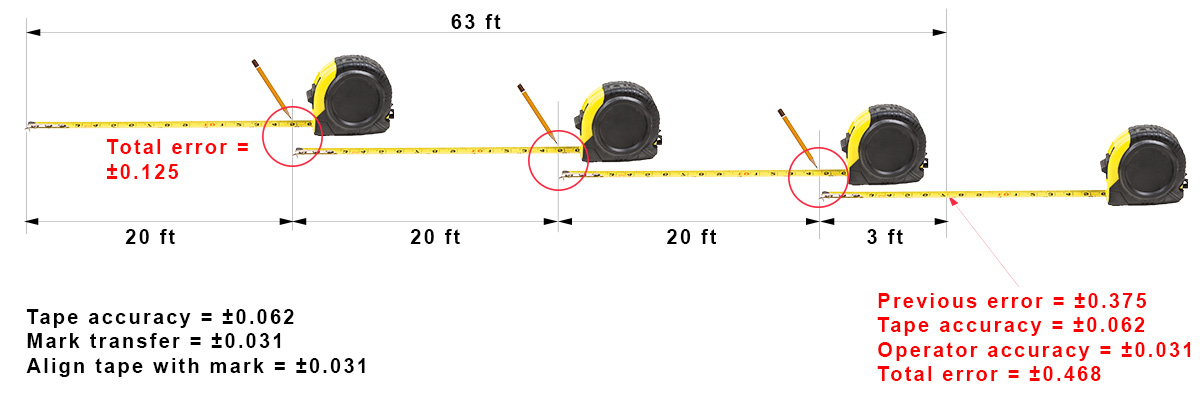
Figure 3: Just like part tolerances, measurement tolerances can also stack up.
But suppose all you have is a 20-foot tape with an accuracy of about one-sixteenth inch (0.063 in.). You will have to make four back-to-back measurements in order to measure 63 feet. However, each time you make one of those moves you are adding three sources of error: tape-measure accuracy of 0.063 in., how accurately you marked the wall with your pencil at the 20 ft mark—call that 0.031 in (about one-thirty-second inch), and how accurately your measurement assistant holds the end of the tape at that mark so that you can extend the tape another 20 ft— call that an additional 0.031 in.
Each time you move the tape, you are adding about one eight inch (0.125 in.) of measurement uncertainty. Do that three times, and add the 0.063 in. tape accuracy and 0.031 operator accuracy for your last reading, and you have a potential of about one half inch error for the overall measurement. This doesn't even include error due to how tightly you pull the tape or even the outside temperature... which also affect the accuracy. Who knew measuring could be so hard?
|
|

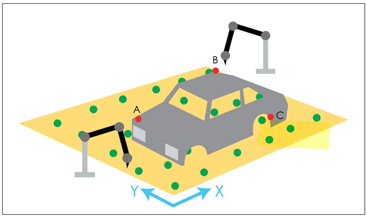
This kind of error can also happen in a manufacturing environment when measuring large objects, such as an entire car frame or an aircraft wing. In those cases it’s often necessary to leap-frog measurement equipment.
Figure 4a shows a Quantum X FaroArm portable measurement arm. This particular FaroArm has a length of about 2 m (6.6 ft), which means a measuring envelope of about a 12 foot sphere, with an accuracy of 23 microns (0.0009 in.).
That’s the accuracy from a measurement taken at one location. But suppose you use the arm in two locations in order to measure the entire car frame (see figure 4b). Each time the arm and its base are moved, the measurement uncertainty increases.
The uncertainty can be calculated, and depending on the purpose of the measurement, the extra uncertainty introduced by leap-frogging may not matter, but it does have to be understood.
In any measurement scenario, a skilled metrologist has to understand the measurement uncertainty of each step and how those uncertainties are compounded.
Operator error
Especially when measuring to tight tolerances, operator skill plays a crucial role in measurement accuracy. Misusing a tool (using too much pressure with a micrometer or caliper, for instance) or not understanding how to measure a particular dimension (inside diameters can be tricky) can cause measurement errors. Depending on how the part is being used, a small error can be greatly magnified.
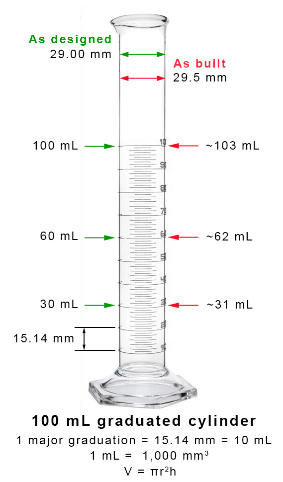 Figure 5: A small difference in the diameter of this graduated cylinder will cause a significant error in the reading as you measure greater and greater volumes. |
In figure 5, we have a graduated cylinder, used for precise liquid measurement. These are made to exacting standards where the inside diameter and distance between marks are tightly controlled. In this 100 mL graduated cylinder, the inside diameter is 29.00 mm and the distance between major marks is 15.14 mm. With a Class B graduated cylinder, the final accuracy of the cylinder should be 1 mL, or 1% at full scale, for a Class A cylinder, it is 0.5 ml, or 0.5%.
Suppose during set up or inspection, the person measuring the inside diameters (ID) of a batch of cylinders is off by 0.5 mm or 500 microns; the inspector reads the ID as being 29.00 mm but in reality it is 29.5 mm and he passes the batch.
That difference is about the thickness of a high-quality business card, but when that error is plugged into the equation for the volume of a cylinder, it translates to about a 3.5% error. That means that at 30 mL, your reading would be off by 1 mL, at 60 mL the error would be about 2 mL, and at 100 mL the error would be greater than 3 mL, three times the stated accuracy of the graduated cylinder. All due to an error no bigger than the thickness of a card.
Assembly error
Although not a measurement error, assembly is another source of error propagation. This can happen when poorly trained assembly people consistently assemble parts incorrectly, measuring equipment aren’t calibrated, or when procedures give inaccurate or confusing instructions. While it might be possible for one part to be assembled incorrectly and not cause any noticeable harm, repeating the error could be catastrophic.
In the video we see a LEGO part that is assembled incorrectly. We can look at how this deforms the base part using a very accurate 3D scanner from Hexagon. When just one part is joined incorrectly, the deformity is invisible to the naked eye, but very obvious on the 3D scan. As more parts are incorrectly assembled, the LEGO base plate begins to noticeably warp.
A more realistic example is aircraft rivets. There are a lot of them in a commercial aircraft, anywhere from 1 million to 1.5 million. How each rivet is installed is critical to aircraft safety. While nothing bad might happen if one rivet in a row of rivets was installed incorrectly, if an entire row of rivets along a wing were all installed incorrectly, the wing could fail over time due to fatigue and cracking at the riveted joints.
Communication error
And then, there is just plain old one hand not knowing what the other was doing. This was the case with the Mars Climate Orbiter crash that happened on September 23, 1999.
Although there was plenty of blame to go around, the main issue was that one piece of software spoke metric, and the other spoke U.S. customary units—often mistakenly called imperial units. When it came to the amount of thrust the orbiter's thrusters were using, one spoke Newtons and the other spoke pound-force, a factor of 4.45 difference.
Although the error didn't start at the very beginning of the journey, it did begin far enough out from Mars, that every time a thruster was fired for course or attitude corrections, the orbiter was knocked off course by a tiny bit due to that error. Over millions of kilometers, the orbiter was so far off course that it entered Mars’ atmosphere xxx miles closer than intended and most likely broke up in the atmosphere.
Measuring the error
The entire point of this series is to look at measurement and how it’s used. Although looking at LEGOs might seem silly (but fun) it does show the capabilities of a couple of types of measurement technology. From microscopic measurements using an Evident microscope, to measuring parts with structured light, to scanning an entire automobile with a laser scanner or portable arm or photogrammetry, we have amazing tools that let us look at what we make in ways never imagined 50 years ago.
But, the tool is only as good as the operator who uses it. Metrologists are trained how to use this equipment properly and to understand the various sources of measurement error and how they affect the entire measurement system.
As this series goes on, you will see some crazy measurements, stuff being measured that you never imagined anyone cared about (the color of orange juice?). In each episode, we will provide a bit more explanation about why measurement is important and how precision measurement helps us keep planes in the air and understand how frogs breathe.
Keep watching The Quality Digest Roadshow.
Add new comment