For decades we were taught to believe that if you ever wanted to measure anything properly, you needed a coordinate measuring machine (CMM). A couple of decades ago, portable arms were released and although they were novel, nothing could compare to the rigidity and accuracy of three linear scales and drives. We were resigned to the fact that any improvement in CMMs would be only incremental. We lived this way for decades. Recently, however, optical CMMs began developing and maturing, to the point that they may have become the revolutionary change the metrology market is looking for.
ADVERTISEMENT |
About the optical CMM technology
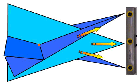
While the technology comes in different “flavors,” most optical CMMs work around a similar principal. For instance, Nikon Metrology’s optical CMM (KCMM) begins with three linear CCD cameras. When light from an active LED is detected, the three cameras triangulate its position in space.
If the cameras pick up two LEDs, they can calculate distance between the two LEDs in three dimensions. If three LEDs are attached to a rigid body, the system can calculate x-y-z-i-j positioning of that body.
To take that further, if we use nine LEDs mounted on a rigid carbon fiber probe with a styli, we can accurately track the position of that probe in a volume up to six meters away from the cameras.
What we have is a CMM that is not bound by the constraints of scales and encoders. However at this point it has only replicated what an arm or a traditional CMM does. This is where the optical CMM’s story begins.
If you continue to add LEDs to your workpiece, you can track x-y-z-i-j-k movement of your part and compensate for it. Simply put, if your workpiece moves, the system doesn’t care. The part or the camera can get bumped and the system will notice the movement in real time and adjust. Here is where the paradigm shift in 3-D measurement comes into play. In a CMM (either traditional or arm), the measurements are in reference to a physical machine coordinate system (MCS). In the optical CMM, the measurements are relative between clusters of LEDs and not necessarily tethered to a fixed location in space.
This concept of dynamic referencing is the cornerstone of usability that an optical CMM can bring to any shop.
You can take the dynamic referencing concept a bit further and move the camera or part on purpose. You might do this to make the part more reachable or to extend the measurement volume over the standard six meters (without leapfrogging).
Let’s take the concept of dynamic referencing to a new elegant level. Nikon Metrology found an automotive application where it was necessary to measure the clearance of a car engine to a closed hood on a finished car. Six LEDs were placed on the car. Three were placed on the hood and three on the frame while the hood was closed. Then the hood was opened and the three LEDs on the hood were turned off (only using the three on the frame). Next the car engine was measured. Since dynamic references were engaged, the system didn’t care that the car was on tires and not stable. Then the LEDs on the frame were turned off and the LEDs on the hood were turned back on. Since the hood was kept open, the system saw a movement in the hood and compensated for it. In other words, the system software closed the hood even though it was still open. The inside of the hood was measured and by using the software, all of the clearance distances were easily obtained.
Adding a laser scanner to the system is as simple as surrounding a laser line scanner with 40 LEDs. This allows for a light, ergonomic laser scanning solution of larger workpieces.
In addition to using the probes, the LEDs themselves can be used to track their positions at speeds up to 1,000 Hz. The LEDs can be mounted to a workpiece and track movement in real time. This methodology has been successfully implemented in earthquake labs, boat towing tanks, and manufacturing test benches, to name only a few.
Successes
Richard Childress Racing is using Nikon Metrology’s optical CMM to measure chassis/suspension geometry for it’s race cars.
They've experienced a 40-percent higher inspection turnaround.
The Volkswagen Group has successfully deployed more than 20 Nikon Metrology optical CMMs for various inspection tasks.
Gehl uses Nikon Metrology optical CMMs in three different facilities to inspect large production fixtures for prototype verification and incoming inspection. Their chassis inspection time has been reduced by 50 percent.
Future
The optical CMM technology is not tethered to incremental growth. It can grow to increase accuracy and volume by adding cameras in different configurations. Further, with core lens/camera corporations becoming active in the technology, development will continue at a rapid pace.
In the end, will an optical CMM replace your bridge CMM? Today, maybe it will only fill a specific need. But in the future, who knows?
Add new comment