Mahr
Thu, 04/23/2026 - 12:02
Social Sharing block
Body
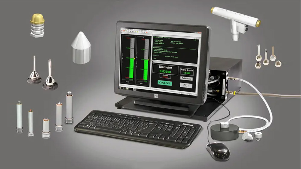
In various industries (or in your shop), there are numerous parts that make use of very small holes. A dozen examples could be listed, but the most common include aerosol cans, needles for delivering fluids and medicines, fuel-injection nozzles, and simple fixed restrictors used to control liquid or airflows.
|
ADVERTISEMENT |
Typically, holes for these types of applications range from 0.1 mm–1 mm in diameter. Some of these small holes aren’t that important. But when it comes to delivering fuel or coatings, the size of the hole may increase or decrease fuel efficiency, or determine the quality of the paint job on your part. And if the delivered product is medicine, hole size might have life-or-death consequences.
…
Want to continue?
Log in or create a FREE account.
By logging in you agree to receive communication from Quality Digest.
Privacy Policy.
Add new comment