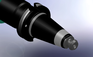
Is your toolholder showing wear in the areas indicated on the toolholder shown?
We’ve been asking this question for some time now, and we know the answer. Normally, close inspection of the tapered area will show a difference in finish at the threaded area aWe examined measuring instruments available in the market place, and determined that there really wasn’t an inexpensive method for measuring taper shank diameter changes. This led to our designing and building the prototype of the Taper Shank Test Fixture. The prototype gauge measures the distance the test fixture moves away from the tool flange, detecting growth in diameter of the toolholder as little as 0.000003 inch.
We purchased three toolholders and three retention knobs of the popular brands, and inspected and compared them to the national standards. We then developed test protocol. First, prior to installation of the retention knob, the test fixture was positioned on the toolholder shank and all three indicators resting on the flange of the toolholder were adjusted to “0.” Second, the test fixture was removed and the retention knob installed to a predetermined torque value. Third, the test fixture was reinstalled, and the average movement of the three test indicators was recorded. We removed the test fixture and the retention knob from the toolholder. The test fixture was reinstalled on the toolholder without a retention knob and the three test indicators were checked to make sure they were still set on “0.” This ensured that the indicators readings were correct and they weren’t moved during the testing of the toolholder. We started the tests at 20 foot/pounds of torque with retention knobs lubricated with light oil. Three retention knobs from the same manufacturer were checked in a row, and all the toolholders were checked in the same order with each retention knob. The retention knobs were checked at torque values of 20 foot/pounds through 100 foot/pounds.
We have now moved into the second generation of the Taper Shank Test Fixture. We contracted with a company that specializes in rebuilding and regrinding spindles to have this new hardened fixture ground. This fixture actually mirrors the toolholder taper, detecting any increase in size over basic, no matter how small the increase or where the distortion occurs along the length of the toolholder. This is significant in that most toolholder manufacturers use air gauges to check the rate of taper at three points of the holder, but not the full length of the taper. Our fixture actually takes an out-of-round condition into account, unlike the air gauge. Our inspection and testing showed that a toolholder, when checked with an air gauge, indicated one AT3 grind limit out of tolerance. Checked again with the Taper Shank Test Fixture, the same toolholder was three AT3 grind limits out. Also, our fixture self-compensates as it won’t show expansion or growth in size until the toolholder expands or deviates enough to register as movement above the grind limit. Keep in mind that toolholder tapers are ground to a total tolerance of 0.000040 of an inch in a class 4 fit and 0.000020 of an inch in a class 3 fit. Growth at the small end of the toolholder results in a poor fit in the large end of the toolholder with the spindle. This in turn results in erratic positioning of the toolholder when loaded into the spindle and inconsistent concentricity at the tool tip.
Our testing with both generations of the test fixture proved that toolholders should be checked for expansion prior to their installation in the machines. The test results revealed that retention knobs started to expand the shanks of the toolholders at a much lower torque value, as low as 20 foot pounds, and that without exception, all toolholders return to their original size after removal of the retention knobs.
Test conclusions for the small end of toolholder:
- In analyzing test data, it’s clear that the burnishing is caused by an expansion of the small end of the toolholder from the pressure of the threads of the retention knobs.
- The torque used in industry to tighten retention knobs expands the tool shank far beyond the grind limits specified by tool manufacturers. In some cases the expansion is 10 to 30 times the grind tolerance.
- Thread finishes had a great deal to do with holder expansion. Parts with better thread finish caused less holder expansion. Parts with rolled thread were less acceptable than parts with cut thread knobs.
- Some retention knobs were not manufactured to the specifications spelled out in the five international standards, and some weren’t even case hardened.
Test conclusions for the area at the gauge line:
- When CNC machine toolholders are changed, the holders stop short of seating properly in the spindle. This distance from the flange to the spindle face varied from 0.0001 to as much as 0.0035 inches.
- When using end mills or slab mills, pressure from the cutting force moves the toolholders, causing them to rub on the side of the spindle 180 degrees from the cutting direction. This has the effect of fretting a second angle at the gauge line of the toolholder.
- Tool run-out causes uneven chip load and reduces tool life; feed rates must be reduced to hold finish and tolerances.
- Run-out and vibration breaks the fine razor edge on carbide tools prematurely.
- High-speed toolholders are balanced before retention knobs are installed. After the retention knobs are installed, the toolholder won’t seat in the same exact position every time the CNC changes tools. This causes the toolholder to become unbalanced in the spindle and contributes to tool life variance from one tool to another in the same cutting operation.
New high torque retention knob design
Using the first generation of our test fixture, we began experimenting with the actual retention knob design. We found, using the fixture, that standard retention knobs inserted into the toolholder with as little as 20 foot/pounds of torque expanded the toolholder shank. Using the newest design of the test fixture, we have proven that the new, high-torque retention knobs, when tightened to the same torque value as standard retention knobs, expand the toolholder shank two- or three- times less than standard knobs. The inclusion of a pilot on the high torque ANSI retention knobs greatly reduces the likelihood of retention knob breakage, especially when the Belleville washers aren’t performing at full strength. The high-torque retention knobs are designed to be balanced dynamically from end to end, which make it much easier to keep balanced toolholders within tight balancing tolerances after installation.
Add new comment