Our PROMISE: Our ads will never cover up content.
Our children thank you.
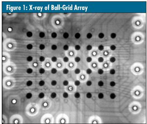
Real-time X-ray inspection systems have been used in quality assurance applications for more than 25 years. In electronics manufacturing, for example, X-ray inspection ensures the registration of drilled holes to internal pads of multilayer printed circuit boards. In electronic assembly applications, X-ray inspection ensures the quality of hidden solder bonds of surface-mounted components such as ball-grid arrays, as seen in figure 1 below.
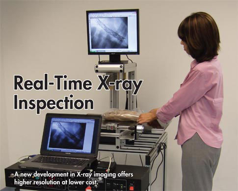
Now real-time X-ray inspection is becoming an important tool for ensuring the quality of many medical devices. These devices incorporate a diversity of materials, including polymers, rubbers, steel, titanium, ceramics, and glass. Real-time systems employ fluoroscopic imaging devices to display the device’s X-ray image in a video format.
There’s a problem, however, and that’s the limited resolution exhibited by the commercial fluoroscopic and digital imaging devices used by most manufacturers. With limited resolution, the systems are unable to magnify the “shadow” image optically. To compensate, system manufacturers have employed increasingly smaller focal spot sources to achieve increased geometric magnification.
As magnification of the radiographic “shadow” is increased geometrically (that is, by moving the specimen toward the radiation source), the physical size of the source, or focal spot, induces a penumbra, or blurry edge, in the X-ray shadow. Mathematically, if the focal spot size of the radiation source is designated by f, and the shadow magnification, which is the ratio of the source-to-shadow plane distance divided by source-to-specimen distance, is designated by m, and the size of the penumbra (the blurry region) is designated by P, then the penumbra blur is related to the focal spot and magnification by the equation P = f (m - 1).
Therefore, to increase magnification without increasing the image blur, manufacturers are compelled to reduce focal spot size, as seen in figure 2 below.
A smaller focal spot creates a clearer shadow.
Presently two types of fluoroscopic imaging devices are commonly used: the cesium iodide (CsI) image intensifier, and the digital flat-panel radiographic imager.
The intrinsic spatial resolution of an imaging device is, in effect, the resolution of the shadow plane. This value can be observed on the video display of the X-ray image of a radiographic resolution target when it’s placed in contact with the input window of the imaging device.
As such, the commercial CsI intensifier displays a spatial resolution of three to four line pairs per millimeter (lp/mm). This resolution limits magnification. That’s due, in part, to limitations of the CsI input scintillator caused by cross-talk, scatter, and, additionally, to demagnifying the photoelectron image.
As for the digital flat-panel imager, it isn’t a true, real-time fluoroscopic imaging device. It’s more like digital film. Unlike the CsI image intensifier, which operates in real time and is capable of limited optical magnification, the flat-panel display consists of a charged-coupled device (CCD) array coated with an X-ray-sensitive scintillation layer, as seen in figure 3, below. The visual image formed by the X-rays striking the scintillation layer is converted into a digital image by the CCD sensors. A control computer composites the CCD signal into a video image. Magnification is determined by the ratio of the size of the CCD array to the video monitor. Flat-panel imagers resolve at 4 lp/mm.
A recently awarded patent describes the medical X-ray analyzer (MXRA) fluoroscopic camera, which can achieve an intrinsic resolution of 15 lp/mm and is capable of magnifying the fluoroscopic image optically up to 40 times without resorting to geometric or digital pixel magnification.
This performance is achieved, in effect, by creating a very smooth shadow plane, positioning the specimen in close proximity to it, and then viewing the intensified shadow image optically with a zooming video camera. When the specimen is in close proximity to the shadow plane, the shadow sharpness is maximized and less influenced by the size of the focal spot. This effect can be seen in figure 4, below.
The closer the object is to its shadow,
the sharper the shadow.
The video camera employs a high- resolution, X-ray scintillator coating coupled to the input window of a nondemagnifying night-vision image intensifier. The fine detail from the scintillator image is intensified 30,000 times at the output window. That image is viewed optically with an autofocusing, analog CCD camera capable of programmable zoom.
The first important advancement realized from this development is a magnified, real-time fluoroscopic X-ray imaging system that isn’t dependent on micro-focal spot size, and the high costs associated with it. In addition, these new systems are compact and can record the fluoroscopic images as either dynamic video or static JPG.
This is a fluoroscopic video made of a small finger. The source is operating at 35 kV to 50 kV at 150 micro Amps, and the X-ray beam is tightly coned to just fill that 50 mm field. There is zero scatter to the operator. The dose rate to the finger while making the video was 25 mR/hr or about 0.4 mR/min.The unique capability of this fluoroscopic camera has allowed the development of X-ray inspection systems for medical device applications. Because of the camera’s compact size and the increased sensitivity it exhibits, fluoroscopic imaging can be achieved at radiation levels lower than normally required for X-ray inspection. The X-ray image can be magnified without moving the specimen toward the X-ray source. A desktop X-ray inspection system produces static and dynamic fluoroscopic images with variable magnification up to 40 times, at power levels of less than 5 watts. This system is presently in use by injection molders to inspect for voids and flaws in catheter hubs as well as low X-ray opacity PEEK (the trade name for polyetheretherketone--a polymer used frequently in molded orthopedic implants, but whose low radiopacity makes detection of voids difficult with standard X-ray methods). The system is portable and can be moved to various areas of a production facility.
These features are useful for monitoring the quality of a stent’s production and development. Because the MXRA fluoroscopic camera requires relatively low exposure levels of radiation, thereby eliminating radiation scatter, access ports to the X-ray chamber permit fluoroscopic video recording of the stent’s deployment from its catheter, as seen in figure 6 below. Rotating the stent with magnified fluoroscopy reveals wire breaks that couldn’t be detected with static imaging. To evaluate a particular stent design, the device is often held in a curved, flexible fixture and subjected to high-frequency flexing by machines designed for this purpose. Afterward, to determine if the particular stent design resulted in fatigue breaks, the fixture containing the stent is placed in the X-ray chamber and slowly rotated. The resulting video can be carefully studied for any evidence of wire breaks.
In another case, the camera’s advanced capabilities were essential to the quality monitoring of a particular stent-type device designed to treat soft, atherosclerotic lesions that may be at risk of rupturing. In this application, it was necessary to record the dynamic deployment mechanism to ensure the design’s performance repeatability. With this design, rather than the stent deploying out of the catheter, the stent-bearing catheter is carefully positioned and a sheath retracted, permitting the stent to expand. The only way to monitor and record design performance was with the magnification and dynamic recording features unique to this type of fluoroscopic camera.
A vena cava filter, also called a blood clot filter, is a large stent-like device that’s catheter-deployed in the vena cava blood vessel to trap life-threatening blood clots, as seen in the inset in figure 5 below. Companies that manufacture these devices need a way of testing to confirm the effectiveness of a particular filter design.
During the research stage, a pig’s vena cava vessel is mounted in a fixture. The filter is deployed into the vessel, and blood clots are then injected into a fluid passing through the vena cava. The filter design’s effectiveness can be evaluated if the trapping action of the filter can be observed. However, the vessel isn’t transparent enough to allow viewing.
To address the problem, a medical device manufacturer commissioned a unique fluoroscopic system that could rotate around the vena cava vessel as blood clots were released and record, fluoroscopically, a video of the trapping action.
Because the relative position of the X-ray source to the camera was fixed, optical magnification of the real-time X-ray image was essential. In addition, it all had to occur at very low radiation exposure levels to eliminate X-ray scatter and ensure operator safety. In other words, the fluoroscopic camera had to simultaneously achieve compactness, high-resolution performance, optical magnification, increased radiation sensitivity, and real-time X-ray recording capability.
The fluoroscopic system designed to satisfy all these requirements consisted of the MXRA camera and a 5-watt X-ray source mounted opposite each other and fixed to a ring gear through which the vena cava passed. A motor-driven spur gear slowly rotated the fluoroscopic assembly, which could also be moved manually along the vena cava’s length. For the first time, trapping the blood clots in vitro could be fluoroscopically observed and recorded, as seen in figure 5.
This technology’s groundbreaking advancements in fluoroscopic imaging continue to find new applications that benefit and improve design and reliability of medical devices. The technology helps ensure the quality of each device’s performance through in vivo study, while saving both animals and researchers from excessive radiation exposure.
These applications are now extending into preclinical stages of medical device development. An open-beam design has recently been used in the preclinical study of a vascular implant. Because of the compactness, magnification, and low level of scattered radiation, the MXRA fluoroscope has become a desirable alternative to existing large and costly clinical C-arm fluoroscopes. It has contributed to the development and quality assurance of life-saving and life-prolonging medical devices.