Featured Product
This Week in Quality Digest Live
Metrology Features
Oak Ridge National Laboratory
Hafnium oxide key to novel applications
David Suttle
What is breakthrough technology really capable of?
Eric Whitley
Robotic efficiency coupled with human intuition yields a fast, accurate, adaptable manufacturing system
InnovMetric Software
One software capable of operating portable metrology equipment and CMMs within the same user interface
Vivian Lam
Four essential reads on how scientists bring the microscopic world into plain sight

More Features

Metrology News
Air-extend/spring-retract moves probe out of the way
Expanded offering includes Smartscope E-series for 3-axis video measurement
Accelerates CAM programming time 80% to make U.S. manufacturers more productive
Enables scanning electron microscopes to perform in situ Raman spectroscopy
Certified for use in Class 1, Zone 0, Zone 1, and Zone 2 locations
Smart-manufacturing data platform collects, presents, and initiates accurate process and metrology data
Supports back-end process control
Quantum nanometrology just got a step closer
Produces clearer images of samples of any shape in which dense areas mask less dense areas

More News

Metris

Metrology

Laser Radar Supports Engineering of Wind Turbine Blade Aerodynamics

Laser radar successfully performed a detailed automatic scan of a 37-meter turbine blade prototype.

Published: Wednesday, October 28, 2009 - 05:00

As Europe sets ambitious targets for energy that is clean and inexhaustible, wind energy is predicted to meet approximately 25 percent of Europe’s power demand within 25 years. Today’s wind turbines measure 70–150 meters and feature bladed rotor diameters of 100 meters or more, translating into a swept air area of 8,000–10,000 square meters. Wind turbines convert wind power into bladed rotor mechanical torque and subsequently into 1.5 to 4 MW of electrical power.


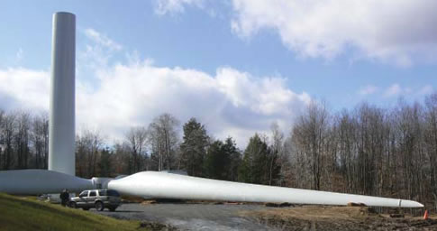
Figure 1: When standing in front of a wind turbine, its impressive size
is striking.

Blade aerodynamic forces responsible for power production must be augmented to maximize energy capture, while adverse aerodynamic loads that fatigue turbine components need to be mitigated to extend machine service life. “To reconcile low weight and high strength, wind turbine blades are made of reinforced plastics,” explains Francky Demeester, business development director at Metris Continental Europe. “However, the immense size of blades and the slight material shrinkage that occurs when working up reinforced plastics make it a real challenge to keep blade shape within tolerance. Metris Laser Radar assists engineering teams in developing wind turbine blade prototypes by inspecting blade surfaces and reporting where and to what extent geometry deviates from CAD.”

Geometry inspection supports blade aerodynamics optimization

Recently, a 37-meter blade prototype of one of the world’s leading wind turbine manufacturer’s was investigated using Metris Laser Radar. During operation, the laser radar system directs a linear infrared laser beam and processes the timing of the reflected laser beam. Accurate fiber optics technology and beam angle verification allow the metrology solution to precisely determine the 3-D coordinates of the surface point being inspected.

The blade was positioned horizontally with the trailing edge directed upward. To keep the blade in position, it was clamped at its rotor connection side and supported half way. As blade prototype construction started off from on an existing blade, only the outer 15.5 meter of the blade required detailed geometry verification. Laser radar and Spatial Analyzer software execute individual point measurements on the concave and convex freeform blade surfaces along a predefined pattern of parallel lines. Measurement resolution increases toward the tip of the blade as shown in figure 2: inter-line measurement resolution (span direction) from 10 mm to 5 mm and intra-line resolution (chord direction) from 10 mm to 1 mm. The previous-generation part of the blade was measured using 500 mm resolution in both directions.

windturbine3.jpg
Figure 2: Graphic representation of geometry inspection tolerance zones, with increasing measurement resolution toward the blade tip

Executing the most suitable part-to-CAD comparison

The blade was divided into six perimeters, governed by the depth of focus of the laser radar. Altogether, these six zones were automatically measured in 15 hours using four different laser radar positions as shown in figure 3. “This resulted in a single point cloud of approximately 5 million measurement points,” says Demeester. “Using Metris Focus Inspection software, a so-called global best fit was performed by fitting the low-density measurement data to blade CAD data. The acquired transformation matrix was applied to the high-density point cloud, and a mesh was created. Graphic reports of the blade’s pressure and suction sides indicate that geometry deviation increases toward the blade tip while opposite deviation characterizes the trailing edge [see figure 4].”


windturbine4.jpg
Figure 3: Six zones—with overlaps of at least 20 cm—were automatically measured in 15 hours using four laser radar positions.

windturbine5.jpg


windturbine6.jpg

Figure 4: Part-to-CAD comparisons using global best fit reveal geometry deviation that increases toward the blade tip while trailing edge shows opposite deviation.

In addition to a global best fit, engineers completed a more comprehensive local best fit, as shown in figure 5. The difference with global best fit is that the high-density measurement data are fitted to CAD instead of the low-density measurement data. As such, the graphic representations of pressure and suction sides provide a much more detailed view on blade geometry deviation. To focus on specific regions on the blade, Focus Inspection even made it possible to calculate a best fit for the leading, central, and trailing areas within each 500 mm region in the span direction of the blade. To accomplish these sectional local best fits, they divided the high-density blade point cloud into 33 subdata sets, which they individually fitted to CAD.


Figure 5: Engineers completed a comprehensive local best fit that provides a detailed view on blade geometry deviation.

Deeper insight support better-engineered blade aerodynamics

The dedicated Turbine Blade analysis module of Focus Inspection offers plenty of other means for engineering teams to gain deeper insight into the geometry of the measured blade. “Cross section diagrams show the comparison between measured and nominal cross section contour lines by applying color codes that highlight the degree of deviation perpendicular to the blade surface [see figure 6]," says Demeester. "In this test campaign, engineers chose to incorporate higher measurement resolution along the leading and trailing edge on a cross section contour line. Focus Inspection software is very helpful in identifying the leading edges and trailing edge thickness at any given percentage of the calculated chord line. Another chart type shows blade twist, i.e., the degree of twist along the span direction of the blade.”

windturbine9.jpg


windturbine10.jpg

Figure 6: Cross section diagrams show cross section contour deviation using color codes that indicate the degree of local geometry deviation.

From a turbine blade engineering standpoint, the various graphic data representations help make well-informed decisions that are critical in creating superior blade prototypes. “There are not too many metrology solutions that are able to timely deliver the detailed geometry information of complete turbine blades,” Demeester concludes. “The speed and accuracy of Metris Laser Radar and powerful data processing capabilities of Focus Inspection make a big difference in blade aerodynamic engineering. The same portable solution is equally capable of running automatic incoming inspection of serial-manufactured turbine-blade sets to guarantee top quality aerodynamic performance.”

Discuss

About The Author

Metris’s picture

Metris

Metris designs, develops, and markets a unique range of 3-D hardware and software inspection systems servicing design and manufacturing industries.

The company’s reliable and innovative metrology solutions cover the full range of measurement volumes required by automotive and aerospace customers, in both fixed and portable configurations and with optical and touch sensors.

Metris headquarters are based in Leuven, Belgium, with additional production and development centers in the United States, Belgium, the United Kingdom, Italy, and China. Metris provides a worldwide network of sales and support offices located in North America, Europe, and Asia. More information on Metris can be found on www.us.metris.com.