Featured Product
This Week in Quality Digest Live
Metrology Features
David Suttle
What is breakthrough technology really capable of?
Eric Whitley
Robotic efficiency coupled with human intuition yields a fast, accurate, adaptable manufacturing system
InnovMetric Software
One software capable of operating portable metrology equipment and CMMs within the same user interface
Vivian Lam
Four essential reads on how scientists bring the microscopic world into plain sight
Chandrakant Isi
Experts in design and manufacturing describe the role of augmented and virtual reality

More Features

Metrology News
Enables scanning electron microscopes to perform in situ Raman spectroscopy
Certified for use in Class 1, Zone 0, Zone 1, and Zone 2 locations
Smart-manufacturing data platform collects, presents, and initiates accurate process and metrology data
Supports back-end process control
Quantum nanometrology just got a step closer
Produces clearer images of samples of any shape in which dense areas mask less dense areas
For processed, frozen, and preprocessed vegetables, confections, and more
Three new single-column models with capacities of 0.5 kN, 1 kN, and 2.5 kN
At Pack Expo Las Vegas, Las Vegas Convention Center, Sept. 11–13, 2023

More News

Ryan E. Day

Metrology

Cutting Down on Airtime

Janicki Industries achieves 35% reduction in required machining by combining 3D measurement arm and laser tracker technology

Published: Tuesday, April 26, 2016 - 10:22

Sponsored Content

W hen you work on projects like NASA’s Space Launch System and deep-space radio telescopes, the opportunity for accolades and large revenues can be great. However, due to the massive scale and demanding tolerances of such projects, the opportunity to have your lunch eaten by wasteful processes is also eminent. Janicki Industries is one company that has successfully addressed that problem.

Founded as Janicki Machine Design in 1993, Janicki Industries is a contract manufacturer to the aerospace industry specializing in aerospace tooling. Janicki Industries designs and builds high-precision parts and tooling for aerospace, marine, energy, space, military, transportation, and architecture customers.
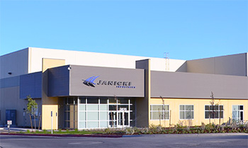
“Today’s tooling market is very competitive. Our suppliers are constantly asking for reduced pricing while still maintaining the same quality they’ve come to expect,” says James Diedesch, senior manufacturing engineer at Janicki Industries. “One way we’re reducing costs is by limiting the amount of nonvalue-added cutting moves during the rough machining stages. These nonvalue-added cutting moves are especially prevalent when dealing with large metal tools. The metal is originally formed as close as possible, but it always varies from the original uniform offset stock models provided by design. Because the exact as-built surface of the tool is not known, the machine path is programmed to move along the nominal surface instead of the as-built surface.”

This means that as a CNC machining tool moves along the designated path, it cuts a high point in the tool material, continues moving to where there may be no material—thus “cutting air”—reaches another high point where it cuts some more material, then cuts more air, then material, etc. The CNC then steps down in the z-axis and cuts again. Eventually it will reach the base material and be cutting material 100 percent of the time, but until then, a lot of time is spent cutting air. On large parts this could mean hours of wasted time.

To address the problem, Janicki uses a FARO Vantage Laser Tracker coupled with a FARO Edge ScanArm HD in a solution known as the FARO TrackArm. Along with InnovMetric Software’s Polyworks software, the solution provides Janicki a high-accuracy 3D scan even for large tools.


“Together they provide greater flexibility for scanning larger parts,” says Diedesch. “We set up a reference system on the tool using SMRs—a target used with laser trackers—and value those targets using the FARO Vantage Laser Tracker. Once that is established we can tie into the tracker’s reference system through Polyworks’ device localization feature. So now, instead of locking into tooling points, you connect the FaroArm (which, for the TrackArm solution, has SMRs attached directly to the FaroArm) to the laser tracker and take a couple of thousand points to localize the arm to the tracker. Once that is established, you start scanning the tool with the integrated laser scanner on the FaroArm.”

FARO TrackArm System

The FARO TrackArm system combines a FARO Laser Tracker with a FARO ScanArm to expand the FaroArm’s working volume, allowing it to be quickly repositioned anywhere within the laser tracker’s measurement range while remaining in the same coordinate system and the same software interface. Users can now unite the laser tracker with the FaroArm into a long-reach, 6-degree-of-freedom probe.

   The FARO Laser Tracker is a very accurate, portable coordinate measuring machine that enables users to build products, optimize processes, and deliver solutions by measuring quickly, simply, and precisely.

   The FARO ScanArm combines all of the advantages of the FaroArm with a hand-held laser scanner (laser line probe) and is the perfect contact/noncontact measurement system. The ScanArm enables users to accurately measure prismatic features with the hard probe, then laser scan sections requiring larger volumes of data—all in one simple tool.

Even with the FaroArm’s 12-ft-diameter reach, on a large tool it may be necessary to move the arm from station to station (leap-frog). However, because the arm is referenced to the tracker, in the end all of the data sets are already prealigned to the same coordinate system and can all be fit together. Individual fitting is not necessary.

“Additionally, unlike leap-frogging with a standalone arm where measurement errors will stack up with each move, the TrackArm system has no stacking error. The nice thing about Polyworks and the FARO TrackArm system is that each time you move, you don't introduce more error to the system,” says Diedesch. “When you are calibrating the device localization you’re going to be about 0.0015 of an inch out of sync between the devices, but when you move the FaroArm, you are not stacking the error, because you establish its position in relation to the tracker.“

Once the scan is complete, the reference object is imported into Polyworks, and a best-fit alignment performed with the scan data, so when the datasets are exported they are in the same position as they are for the NC program. The NC program can now be developed for the as-built surface instead of the nominal surface.

“The particular tool path we are using is cavity milling and it requires a stock model,” says Diedesch. “With a polygonal scanned stock model this tool path knows exactly where all the stock is rather than giving it a uniform offset and having it cut a high corner, then cut nothing, then cut the corner again. Now it slices layers based on the tool engagement depth and focuses on the high corners and waits until it gets to the proper z-level depth before it engages in the low spot of the tool. It’s been a real savings in machine time as a result.”

“The result of this solution is roughly a 35-percent reduction in machining,” says Diedesch. Depending on the size of the tool, he figures the company can save up to 20 hours per tool.

Discuss

About The Author

Ryan E. Day’s picture

Ryan E. Day

Ryan E. Day is Quality Digest’s project manager and senior editor for solution-based reporting, which brings together those seeking business improvement solutions and solution providers. Day has spent the last decade researching and interviewing top business leaders and continuous improvement experts at companies like Sakor, Ford, Merchandize Liquidators, Olympus, 3D Systems, Hexagon, Intertek, InfinityQS, Johnson Controls, FARO, and Eckel Industries. Most of his reporting is done with the help of his 20 lb tabby cat at his side.