Featured Product
This Week in Quality Digest Live
Management Features
Jake Mazulewicz
Three tips from high-reliability organizations
Dave Gilson
Getting out of the boardroom for a stroll changes how women navigate
Bob Ferrone
Saving the planet and bolstering the bottom line
Jeanne Quimby
Kids can be the source of new ideas
Matt Fieldman
Vocational programs and apprenticeships show the way

More Features

Management News
How to drive productivity with a universal and powerful 3D inspection software
Research commissioned by the Aerospace & Defense PLM Action Group with Eurostep and leading PLM providers
Improved design of polarization-independent beam splitters
New industry-recognized guidelines for manufacturing jobs
ASQ will address absence of internationally recognized ESG benchmarks
Helping organizations improve quality and performance
Leading technologies empowering the next generation of 3D engineering software solutions
EstateSpace offers digital estate management system

More News

Ryan E. Day

Management

Conquering the 100% In-Line Inspection Challenge

The FARO Cobalt Array Imager helps VRSI and Dynacraft get it done

Published: Tuesday, November 14, 2017 - 13:02

Sponsored Content

Headquartered in Algona, Washington, Dynacraft is a diversified global manufacturer of PACCAR medium and heavy-duty truck parts sold under the Kenworth, Peterbilt, and DAF nameplates. For more than 40 years, Dynacraft has provided the company’s truck manufacturing divisions and PACCAR parts division with high-quality components, subassemblies, and specialized services.

The challenge

“One of the requirements going into the new 2017 emission systems, which we are producing currently, was a requirement from our supplier quality group to do a 100-percent inspection of the emissions assemblies,” explains Mario Caudillo, production quality engineer at Dynacraft. “We were performing a standard sampling plan up to that point, so it was quite a challenge to try to go from a sample plan to 100-percent inspection.”

Although Dynacraft runs more than 200 assemblies daily through its production line, one manual measuring arm and a few technicians were sufficient to keep up with sample testing. It took very little introspection, however, for the Dynacraft quality team to determine there was absolutely no way they could do 100-percent inspection with their existing process. An automated solution would be required to meet the customers’ expectations.

Asking the right questions

Having worked at a major OEM prior to his position with Dynacraft, Caudillo had some experience with equipment that could help with the dilemma. It was just a matter of finding the right company with the right individuals to be able to bring the project forward.

“I had talked to a few companies about this project and due to some technological constraints on their end, they could not provide what we were asking for,” says Caudillo. “When I approached Variation Reduction Solutions, Inc. (VRSI) and started talking with Evan Asher and Mike Kleemann, they were asking the right questions to be able to initiate and move this project from ground floor to application.”

Building things that build things

With a large team of highly experienced specialists, VRSI has been providing customers with state-of-the-art integrated solutions for vision, metrology, industrial robot guidance, and automated inspection since 1998.

“Most everything that our group does is at least semi-custom,” says Evan Asher, project engineer at VRSI. “Each project is modified specifically to the customer’s application and needs. We have some projects that are similar to others, but inevitably every customer has a slightly different process with slightly different requirements  Depending on what the problem is, we tailor the solution to that.”

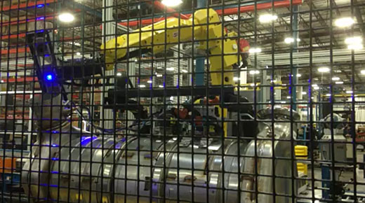
The ideal solution for Dynacraft would have to conform to a size profile allowing it to fit within an in-line work cell on the shop floor, be fully automated, and have the ability to measure a 6 ft-long canister with 50 to 60 variations—all within 65 seconds.

Choosing the right system components

“When a project requires integrating metrology with factory automation, there’s often a significant system engineering component,” explains Mike Kleemann, chief engineer and manager of the Aerospace group at VRSI. “We start with the requirements, and then work backward to identify the combinations of measurement, automation, control, and integration elements that need to come together for an optimal solution.”

One of the system components that VRSI employed was a FANUC robot arm. For the metrology end of things, they chose the FARO Cobalt Array Imager.

Cobalt Array Imager

“Part of the reason we like to work with FARO in general is just because they’re a very reliable supplier,” says Asher. “With the Cobalt, we found that both the accuracy and the field of view fit right into this application. And then once we started using it, it was very easy. It’s plug and play, you plug it into the computer and you can pretty much start rolling right away, so it proved to be relatively seamless. I would argue that the more straightforward part of the project was implementing the Cobalt.”

FARO Cobalt Array Imager

Variations of surface finishes on the same assembly were also a consideration when choosing a scanner.

“The surface [of the emission assembly] has multiple metal finishes,” explains Asher. “Some are shiny, some are dull, and some are kind of in the middle, more like black dull metal. Also, the angle at which the Cobalt has to measure the surface [due to space restrictions] also contributes to a difference. So, what we did was, for each of those positions we dialed into a different exposure setting. Sometimes one exposure setting was sufficient, sometimes we needed multiple exposure settings. To capture certain features effectively, we actually shoot three different exposures to achieve a proper measurement.”

The high dynamic range of the Cobalt, and its ability to measure shiny surfaces, make it a natural choice for in-line factory metrology solutions.

Click here to schedule a FREE 15-minute personalized live web demo of the Cobalt Array Imager
or call FARO at 800–736–0234

Fitting in with manufacturing flow

“One priority for us was to be able to get the datums scheme according to their geometric dimensioning and tolerancing (GD&T) of the print,” explains Caudillo. “The location of the datum points on the assembly are very difficult to obtain because of where they are placed within the assembly. That is something that VRSI was able to do very well with the Cobalt system and the robot.”

Managing production-floor space requirements is no small challenge when designing a 100-percent inspection system.

“Two of the four features we had to measure were in very tight quarters,” says Asher. “In order to measure all the features, the Cobalt  had to be at very specific angle. Between the field of view of the sensor, and the articulation of the robot, we were able to find the appropriate position to get those features.”

Maximizing system flexibility for mixed product lines

One of the most difficult pieces on this project was trying to determine what would be the best way to capture all the different variations of position of the inlet and outlet of these assemblies. The variations all had distinctive inlet and outlet locations, as far as the x and y configuration of the location of the inlet and outlet ports.

“The Cobalt sensor really gave us a lot of flexibility,” says Asher. “Due to the volume of the Cobalt sensor’s field of view, all of the parts that we were measuring, although at slightly different positions, fit within the volume of that field of view. Even though we’re processing different parts, from the Cobalt point of view, we were able to use just one robot Cobalt position to measure over twenty different configurations in that one position, instead of having 20 different robot positions.”

In other words, the system can get the data on 50 to 60 variations with six robot positions instead of hundreds. This trick saves time, effort, and the number of routines that they would have to write and how many routines would need to run to capture all the data necessary.

At each of the robot positions, the Cobalt gathers data and creates a point cloud. The related point clouds must be “stitched” together to form a complete data set for each emissions assembly. To stitch those point clouds together accurately, the Cobalt positions are registered during the initial setup process. This was accomplished by using a FARO Vantage laser tracker.

“Robot calibration usually means that you use laser tracker data to improve the volumetric accuracy of a robot by updating its kinematic model,” explains Kleemann. “We didn’t do that here because there were a small number of discrete positions. The Vantage laser tracker was used to initially register the robot positions, and then the system relies on the robot’s repeatability to maintain those positions going forward. For this application, it’s an effective and efficient approach.”

“From the Cobalt’s point of view, it just measures four arbitrary point clouds. We then used a FARO Vantage laser tracker to register those positions before any parts come into the cell,” says Asher. “That way, you can mesh it all together to get an accurate depiction of a part.

“There is no question that this application would not function without the initial laser tracker registration,” he says. “That is a requirement for the process.”

The automation situation

The Dynacraft facility runs 26 production lines. Twenty-four of them are almost entirely manual, one other being semiautomatic—one operator and one robot. And then there’s the new QC line.

Video: VRSI designed this automated measurement system for Dynacraft, utilizing FARO’s Cobalt Array Imager.

“This is actually the first project with the most automation for our facility,” admits Caudillo. “Our facility is labor-intensive, so when we were tackling this project, we wanted to make that transition from being a manual, labor-intensive process to one that is highly automated.

“This system is self-sufficient,” says Caudillo. “There is no operator involvement at all. The system will determine whether the part is good or bad, pass or fail, and then it will send that information to the end of the line to tell our operators in pack-out, whether it’s a good part or bad part. If it's a good part, it continues through the pack-out process. If it is a bad part, the VRSI system will reroute that assembly manually to a rework station, where it will get reworked and then remeasured manually to verify that it is good; then it’ll return to the pack-out to ship out to our customer.”

Minimizing takt time

Perhaps the biggest priority of the project was to meet the takt, or cycle time, requirement.

“Sixty-five seconds is the takt/cycle time that the line has to produce a part to be able to meet the demand of our customer,” says Caudillo. “Those 65 seconds will allow us to build roughly 240 to 250 assemblies on a daily basis. Anything above that 65-second mark means that the line is not meeting the customer demands.”

The efficient automation of product feed and measurement routine was a huge factor in developing a system that could meet production cycle time. Another key factor in time savings was the Cobalt’s on-board processing, wherein the point cloud is calculated within the Cobalt itself.

“The Cobalt’s on-board processing made the application so seamless,” says Asher. “Once you have the Cobalt in position and measure, that point cloud is generated in about three or four seconds. Being that quick was extremely important because that allows more time for the robot to move. The robot doesn’t have to move at a high speed because we have some flexibility thanks to the speed of the Cobalt.

Bonus benefit

Whether your QC process is sample-based or 100-percent inspection like the VRSI inspection station, it could be said that its core function is catching bad parts. But that is just a starting point. The Dynacraft team uses the “bad-part data” in a positive way.

“We suspected some issues with supplier parts,” admits Caudill. “We have a supply base that produces different parts for different areas of our facility. Usually if you find a bad part in one area, you will find that same manufacturer having bad parts in another. And so those issues came forth, and they were visible when we started using the statistical process control (SPC) system with data from our 100-percent inspection line.

“This system is now allowing us to drive those issues back to our supply base and try to help them improve,” he says. “When that came forth, they were very happy because, again, now we have data to show to our supply base: ‘Hey, you’ve got issues. How can we help you to improve?’ I don’t think it was something that was a forethought before this project. I think it just kind of showed and presented itself. And then we took it and we ran with it.”

In essence, the 100-percent inspection protocol helps suppliers improve their own organization as their quality control gets tighter.

Evaluating the project

After about five months of running the system in regular production, the Dynacraft team had data it was confident in, and a pretty good understanding of the capabilities of its new QC system. What’s their assessment?

“We’re very pleased with what we have,” reveals Caudillo. “What our quality techs were doing via our sample plan, on a good day they could capture roughly 25 units in an eight-hour shift. So, doing the math, it would take them roughly anywhere from 20 to 30 minutes per assembly to measure. That’s why when our customers wanted to go to 100-percent inspection, we kind of scratched our heads and said, ‘How are we going to pull this off?’ And we knew that the only solution would be something in-process, in-line, to be able to do what they were asking for. If we were going to do the same thing via a manual process, we would have to increase our headcount within the quality department by at least five or six heads per shift to be able to capture the kind of data that we’re currently capturing.”

And would that be a profitable proposition?

“Not at all,” he says.

The 100-percent inspection differentiator

Although at the time of this writing, 100-percent inspection is the exception rather than the rule in manufacturing, it is being called for more and more. It is already the norm in much of aerospace and medical device industries. As OEMs seek to mitigate risk factors, and suppliers seek to differentiate their organizations from the competition, no doubt it will come to the forefront as the premium QC process.

“One of the things that Dynacraft works on is continually improving the quality of our products,” says Caudillo. “So, in the overall scheme of things, not only are we meeting the demand of our customer [for one hundred percent inspection], but we are helping ourselves. By doing this, we ensure that we are building quality products 100 percent of the time through this particular process.”

He sums it up like this: “When you do 100-percent inspection, you’re basically saying, “Yeah, everything that we produce and ship is according to our customer’s demand.”

Discuss

About The Author

Ryan E. Day’s picture

Ryan E. Day

Ryan E. Day is Quality Digest’s project manager and senior editor for solution-based reporting, which brings together those seeking business improvement solutions and solution providers. Day has spent the last decade researching and interviewing top business leaders and continuous improvement experts at companies like Sakor, Ford, Merchandize Liquidators, Olympus, 3D Systems, Hexagon, Intertek, InfinityQS, Johnson Controls, FARO, and Eckel Industries. Most of his reporting is done with the help of his 20 lb tabby cat at his side.