In 1988, a small company began developing and supplying electronic instruments that automatically compensate for temperature-induced errors in industrial gages that are used to make precision dimensional measurements. Its products are now in use worldwide, improving factories and workshops that machine metal parts to tight tolerances.
ADVERTISEMENT |
ISO 1, the first standard issued by the International Organization for Standardization (ISO), specifies the standard reference temperature for geometrical product specification and verification, which is fixed at 20°C (68°F). This temperature can be difficult to maintain in a manufacturing environment, and all the elements of a measuring system (workpiece, master, and gage fixture) can be affected by thermal influences.
When certain parts are measured after precision machining or cleaning operations, or after otherwise being exposed to temperatures other than the reference temperature (20°C/68°F), their dimensions can be significantly altered by thermal expansion or contraction. Gage fixtures and masters might also not be at reference temperature. The result will be that erroneous measurements will be made unless this is taken into consideration.
However, normalization to 20°C/68°F before measurement can take precious time. The quickest and most economic option is to compensate for those errors in real time while taking measurements.
Albion Devices has successfully delivered and maintained literally thousands of so-called “three element” temperature compensation systems. They are used in gages to determine true size at reference temperature of machined components such as automotive pistons and pins; crankshaft journals; engine and transmission bores; railroad axle journals; bearing rings; differential carrier parts; and large forged parts such as marine gears and shafts, and turbine journals.
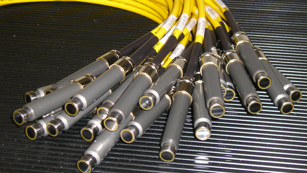
Obtaining the best results from an electronic temperature compensation system requires several inputs. Coefficients of expansion (COE) of workpiece, master, and gage fixture or frame (elements) are programmed into the controller, along with relevant dimensional data relating to the workpiece. Live temperatures of each of the elements are collected from purpose-designed industrial sensors and transmitted to a microcontroller during operation. The controller computes a net correction for thermal errors in real time, and this solution is then added to or subtracted from the gaged dimension to arrive at the temperature-corrected size of the workpiece.
The coefficients of expansion of master and workpiece can be reasonably estimated from published materials. For any given part, subject to its geometry, net effect COEs might not always be empirically identical to the referenced publication and can be modified if necessary by testing in the gaging system.
It can be more difficult to estimate the effective net COE of gage fixtures or frames because they are often made of several components involving different materials. Also, each piece might adversely interact mechanically with its neighbor and fasteners as temperatures change. Again, testing in the gage can result in determining an acceptable COE value.
By simultaneously compensating for thermal effects in the elements of a measuring system in real time, it has been possible to eliminate 95% or more of thermal error in dimensional measuring systems on the shop floor. The result is that displayed measurements reflect the predicted dimension of a measured part at 20°C/68°F to within a few percentage points. The benefits of this in mass and precision production are experienced in improved quality control, reduced scrap and rework, improved process control, reduced warranty costs, and increased customer satisfaction. Invariably, users have become repeat buyers and have enjoyed rapid payback of their investment.
Results of tests conducted by users have consistently shown improvements in process control. Below, Figure 4 shows data from one such test on a gage that compares results from taking measurements without applying temperature compensation and with temperature compensation applied. Note the difference in Cp and Cpk values as well as the differing shape and concentration of the histograms. A process that appeared to be incapable due to thermal effects, and might lead to needless and erroneous operator correction, is in fact quite capable.
A demonstration of the success in eliminating at least 95% of thermal error is illustrated by the graph in Figure 5. It displays the dimensional readings of a gage as it was used to measure a part at different temperatures. The first reading is at shop temperature. The part was then heated, and as it cooled it was again measured repeatedly. The temperature compensation system can be put into a mode that allows both compensated and noncompensated dimensions to be read on its screen simultaneously.
The red curve on the graph shows the dimensions that were displayed by the gage when temperature compensation wasn’t being applied. The blue curve represents the temperature-compensated dimension that was showing at the same time as the respective noncompensated reading was taken.
The summary below the graph shows the average correction to the noncompensated dimension and the total temperature range of the part during the test. Note that the blue, compensated curve correlates closely with the green curve, which represents the original size when measured for the first time, when the part was at ambient shop temperature.
Temperature compensation is not a recommended addition to all gages. It applies only to those situations where tolerances in relation to nominal size are tight enough that thermal errors are consequential. By applying a reasonable COE, expected temperature range at which measurements will be taken, and nominal size of dimension to be measured, a calculation can determine the likelihood of benefit from eliminating the majority of thermal error exposure by using this technology.
Add new comment