Featured Product
This Week in Quality Digest Live
CMSC Features
Etienne Nichols
What’s the difference?
Atul Minocha
It’s all about ROI
Ryan E. Day
September Speaker Series in review
Ryan E. Day
Realigning a cornerstone of industry
David H. Parker
Practical implications for electronic distance measurement

More Features

CMSC News
Expands simulations for electrification and aerospace design
VSL hosts special edition of show at new center in Rotterdam
Latest line touts comprehensive coverage, ease of use
Blackfly S GigE line grows
Voting for 2022–2023 term will open at CMSC 2022 starting July 25
New facility in Toronto area will showcase multiple Hexagon product lines
API division named ‘Top External Provider 2018’
Exact Metrology selected for project
Faster and more powerful than ever before

More News

Myles Puentes, Shawn Haar, Paul Jeffers, Predrag Sekulic, and Mary Liang

Myles Puentes, Shawn Haar, Paul Jeffers, Predrag Sekulic, and Mary Liang’s default image

CMSC

DKIST’s Journey Using Laser Trackers

Important lessons learned

Published: Thursday, November 7, 2019 - 21:22

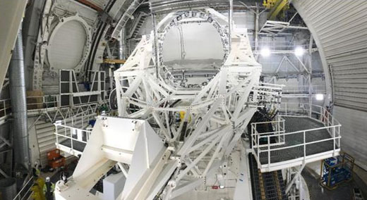
The Daniel K. Inouye Solar Telescope (DKIST) is strategically constructed on the summit of Haleakala, 10,023 ft above sea level, which is an ideal vantage point for solar observations. Site construction started in 2012 and moved into the integration, testing, and commissioning (IT&C) phase during the summer of 2019. DKIST will reveal features three times smaller than anything we can see on the Sun today and will do so multiple times a second.

Mounted on the telescope mount assembly (TMA) and measuring in at 4 m is the world’s largest off-axis parabolic primary mirror along with five other feed optics and the thermal system. Following the TMA is the rotating coudé laboratory, which houses the scientific instruments. All of the aforementioned elements need to be optically aligned as well as mechanically aligned to the mechanical axis of the TMA, a theoretical location whose location and motion is derived by solar altitude and azimuth. Using today’s laser tracking technologies and metrology software has made it possible to survey and interpret large articulating mechanical structures like DKIST’s telescope mount, optics, and thermal systems.

Nomenclature

• DKIST: Daniel K. Inouye Solar Telescope
• M1: DKIST primary optic
• M2: DKIST secondary optic
• M3: DKIST tertiary optic
• NSO: National Solar Observatory
• OSS: Optical support structure
• SMR: Spherically mounted retroreflector
• TCS: Telescope coordinate system
• TMA: Telescope mount assembly
• USMN: Unified Spatial Metrology Networks
• WFS: Wave front sensor

Overview of TMA, view 11

Overview of TMA, view 2

Hardware and software description

At DKIST we have chosen to use a pair of laser trackers: the API Omnitrac 2 and the FARO VantageE coupled with New River Kinematics SpatialAnalyzer (SA) as our software package. Due to the TMA’s unconventional structural design, we are able to utilize the versatile nature of the trackers’ flexibility and accuracy by mounting them in unorthodox locations on the TMA with magnetic bases, custom fixtures, and tripods to gain visibility where it is needed. The structure is often rotated in azimuth as well as altitude with the trackers taking measurements throughout the entirety of the rotation. SA was used because of its clear interfaces between both API and FARO hardware as well as powerful features such as point uncertainty calculations, Unified Spatial Metrology Networks (USMN), and Best Fit analysis between point groups. These features are utilized in complex circumstances like ours where it’s necessary to continuously link new tracker locations with preexisting monument measurements as well as expanding large data sets to existing files.

Azimuth bearing alignment

The first major alignment activity of the TMA started with the azimuth bearing rails. The site build specifications requested to hold planar and coaxial alignment of the bearing rails with the coudé rotator floor, 9.6 m below. The tolerances that were held are planar within 0.050 mm and coaxial 0.050 mm. In addition to these tolerances, the accuracy in which these two concentric rails are aligned drove the accuracy levels of the systems in the proceeding stages of the TMA construction to keep the overall tolerance yield to a minimum. Once the azimuth rails are torqued to specification and assembly continued, there would have been no practical way to adjust for out-of-specification errors in the alignment.

As seen in figure 1, a yellow lever arm (provided by the telescope manufacturer) acted as an inspection gauge. It is positioned to rotate around center and rides along the rails on a truck with a digital indicator on the adjacent end. At every 10° a measurement was made for both axial and radial runouts with both the lever arm and laser tracker. Although the tracker data was sufficient for the tolerances given, having a mechanical form of inspection to verify the trackers findings became useful for such a keystone alignment.

Mount Bearing Radial Alignment Process

Figure 1: Yellow lever arm measuring axial and planar runout of the azimuth bearing

Lessons learned

Each of the inner and outer bearing rails consist of 18 segments, the inner having a 5,000 mm diameter and the outer measuring in at a 9,200 mm diameter. As the team approached the tracker’s accuracy, controlling the environment became critical during data collection. Lights were powered down and all doors and windows were closed to reduce the amount of turbulence in the air and to limit any interference with the laser. These actions also assisted in reducing the amount of thermal expansion throughout the measurement process of the inner peer on which the bearing rails ultimately mount. Each ring assembly was kept to a total axial runout of .035 mm and a total radial runout of .05 mm.

Altitude bearings alignment

Due to the precise machining practices conducted during the manufacturing of the altitude tower interfaces, alignment of the altitude towers and their bearings was accomplished without great effort. The precise positioning of the azimuth bearing played a keystone role in the erecting of the remaining TMA structure.

The alignment of the towers in relation to the azimuth bearing was made possible due to the use of the laser tracker and utilizing its ability to relocate into abnormal positions, all while referencing back to permanent SMR monuments mounted strategically to link tracker locations and their previously surveyed points. An example of SA’s Best Fit report for relocating a new instrument by using these permanent monuments can be seen in figure 2. As construction of the TMA continued, new permanent monuments above the floor would be placed in reference to monuments under the floor to continuously link the data in SA.

Figure 2: Example of a SA Best Fit report

Once the tracker was able to be positioned to a new location, the tops of the altitude towers, where the altitude bearings mate, were surveyed for possible shimming and/or translation to fall into specification. With the error between plane normals accounting for only 0.012°, it was determined to be sufficient to move forward with the bearing trunnion coaxial alignment. The trunnion bore machining and surface tolerances served as a useful surface to compare. The desired tolerance is that the two cylinders of the trunnion be within 0.250 mm concentric of each other.

Figure 3 offers a glance at the magnitude of the TMA structure being placed onto the azimuth bearing rails below. When complete, the TMA is an approximately 220-ton rotating mass with the two altitude towers comprising a majority of that weight.

Altitude Motor Installation

Figure 3: Assembly of the altitude towers and bearings

Constructing the TCS

Like a CMM inspection of any given part, a coordinate system, or frame of reference, must be defined by controlling the six degrees of freedom to determine relative features of the part or system. Again, an obstacle for DKIST is that our TMA system is a 220-ton, 14.0-m-tall, 12.5-m-wide, rotating structure with limited visibility for the laser trackers. All of these factors had to be taken into great consideration to avoid jeopardizing the laser tracker’s accuracy.

The primary goal here was to locate the mechanical axis of rotation of the fully weighted TMA around the azimuth bearings previously mentioned. Azimuth rotation will define the Z axis, while rotations around altitude will define the X axis of the coordinate system. The intersection of these two axes were used to define the TCS. Once the TCS had been defined, we placed six permanent monument SMR nests in strategic locations for the trackers to link to in defining multiple tracker positions in relation to the TCS in SA. Defining these coordinates then allowed us to start the inspection of all of the mating surfaces of the optics and thermal system mounting positions for integration, testing, and commissioning.

Defining azimuth axis of rotation

As cited before, the azimuth center of rotations defines the Z axis of the TCS. At this point of the TMA assembly, the motor drives necessary to rotate the TMA were powered. Finding a position for the laser tracker to obtain the most effective field of view during rotation as well as SMR mounting locations became an apparent hurdle to gathering the most data possible.

Initially we wanted to verify the stability of the tracker on its tripod during rotation. We did this by incrementally rotating while using SA’s Instrument Drift Check feature as well as observing a watch window on a single point. The engineering team then agreed upon a position on the telescope floor for the laser tracker that would allow 120° of visibility on one side and 30° of rotation of the other. Four SMRs mounted on the static floor were positioned to give an overlapping 360° view of the rotation. Both techniques showed little to no vibration or flexing to either the structure or the tracker tripod. Satisfied by the results, the feet of the tripod were secured to the floor using hot-glue.

Keeping the tracker stationary, we conducted four rotations, one rotation for each of the SMRs on the static floor while pausing every 5° to take measurements. Between each of the four rotations, an Instrument Drift Check was conducted using SMR monuments on the towers to verify the stability through the measurement process. Figure 4 gives a SA perspective of this arrangement.

Figure 4: An SA view of the laser tacker in position to measure azimuth rotation

Due to the nonplanar nature of the static floor, the four measured SMR positions were used separately to construct circles whose normals would determine the center of rotation and effectively define the Z axis. The four rotations were assessed by analyzing the level of point uncertainty as a result of the environment and distance from the tracker. SA’s uncertainty determination concluded that our measurements all fell below 0.084 mm measurement uncertainty. One of the four SMR rotations was found to be unfit and discarded. Although relatively coaxial, the remaining three centers of rotations vary. This is a result of measurement uncertainty, SMR reflective conditions, and temperature variations throughout the measurement process. After carefully reviewing the spread of the remaining three center positions normal, it was decided that the rotation 2s normal would be most adequate to define the TMA’s mechanical coordinate system’s Z axis.

Defining the altitude rotational axis

As previously explained, the altitude rotational axis will define the mechanical X axis. This will be conducted in a similar fashion as the Z axis in azimuth. First a tracker position was surveyed to allow a clear sight of four SMRs, two on each of the large counter weights on the TMA, for total rotation of 94°. Again, stability of the instrument was verified using the same methods used in azimuth rotations. Figure 5 provides an SA perspective of the tracker’s location and points measured during rotation in reference to the SolidWorks model.

Figure 5: An SA view of the laser tacker in position to measure altitude rotation, trial 1

Measurements of the SMR positions were taken every 5°, pausing at each time a measurement was taken. Points were taken during the rotation from zenith to horizon and from horizon to zenith to scan for anomalies in the collected data later. Fitted points were then used for the construction of circles, cardinal points, and their projected vector to resemble the rotational axis of the structure. The data collected was found to be repeatable throughout both rotation directions on the pair of counterweights but also unreliable. The variations in each of the four circle’s centers were concluded to be too great. We decided to neglect these data.

It was found that the 3-m distance of the SMRs from the axis of rotation on the counterweights lead us to witness the structure flexing during the rotations through the gravity field. The team decided to move the SMRs closer to the trunnion hub to eliminate the influence of the flexing structure to the data, as seen in figure 6. Measurement methods were repeated and concluded to be repeatable and reliable. The mechanical altitude axis of rotation, X, is defined by the closest perpendicular circle centers to the Z axis.

Figure 6: An SA view of the laser tacker in position to measure altitude rotation, trial two


Mechanical/optical alignment

Information on the telescope optics

The primary mirror (M1) is an off-axis parabolic mirror. This means the surface of the mirror is parabolic in shape but only an off-axis potion of the parent mirror is used causing the collimated input beam to focus at an angle. The optical ray traces through the center of the optic to the center of the beam’s focus and the parent axis are separate. SA was very helpful in integrating the optical design and ray trace from Zemax, the TCS gut ray, and to provide the frame at the mechanical interface for alignment.

Alignment process

The alignment of the large optics started very early during the fabrication process when polishing the primary mirror at University of Arizona. There they placed four SMR nests on the outer diameter of the primary mirror. After the polishing process was finished, they were able relate those four SMR locations to the optical parent axis, the gut ray, the optical surface, and focus distance.2

The next challenge was placing the primary mirror SMR location data into our TCS. This effort required us to measure the location of the mechanical interfaces on the telescope for M1, M2, and M3. We then did a best fit in SA to place M1, M2, and M3 to a location that provided enough room for a rough mechanical alignment then fine adjustments using shims.

The primary mirror cell is the mount for M1, houses the gravitational sag compensating actuators, and provides active optics for low-order aberrations. For the initial installation of the primary mirror cell, we placed it at the center of the mechanical range of travel as seen in figure 7.3 Once installed, measurements indicated the primary mirror cell was placed in an erroneous position due to the use of an incorrect frame of reference in SA when creating the best fit numbers. The center of the optic was used as the reference frame instead of the frame at the center of the mechanical interface.

   Figure 7: Primary mirror cell on its transportation cart before mating to the TMA

With the primary mirror installed using the correct reference in SA, the best fit from our measurements were input into the optical design software, Zemax. Because the tolerance of M1’s position is very tight and difficult to achieve, M2’s modified position was recalculated in Zemax to minimize the aberrations and to preserve the gut ray location for other optical instruments further in the system. This provided a more accurate position of M2 and the general position of the wavefront sensor (WFS) used for initial nighttime sky testing, as seen in figure 8.

Figure 8: Laser tracker mounted between M1 and M2 to check alignment before nighttime testing

On sky testing, the WFS is the final authority of the optical alignment. The resultant wavefront error considers all errors from the optical fabrication, optical alignment, thermal expansion of the optics and the TMA, structural vibrations, and atmospheric turbulence as seen in figure 9.4

The WFS was mounted on a hexapod which provided six degrees of freedom (as seen in figure 10), by translation and rotation about X, Y, and Z to minimize the wavefront error. This WFS was placed at both the prime focus and the Gregorian focus.5

Figure 9: Light path of the TMA optics


Figure 10: FARO laser tracker aligning the SHW at the M3 location

Lessons learned during the M1 and M2 alignment process

A critical lesson learned was attention to the reference frame. Zemax had a preference of using the parent parabolic surface, not the physical dimension of M1 as the reference. Reference options in SA were the mechanical interface frame or the telescope coordinate system frame. By pulling all the data from various design software and choosing the correct reference frame, the team was able to calculate the correct shim thickness and align the system meeting the wavefront error specifications.

Our second lesson learned was proper placement of SMRs. Initial primary mirror cell installation used the SMRs on the front corner of the mirror cell instead of SMRs on the mirror itself. Although these locations made it simpler to take measurements, this indirect measurement of the mirror was less accurate than we needed due to the SMR spacing being too short.

The third lesson learned is data organization and creating an efficient labeling system to expedite processes. As the primary mirror cell was installed, measurements were taken as a guide. Unknowingly, there was structural deflection due to mirror cart pushing on the OSS and also due to the weight of the mirror cart itself causing unrepeatable measurements. This resulted in installation of M1, removal of all installation tooling, allowing the OSS to deflect, taking measurements to confirm the location and then repeating the process until specifications were met. By improving our data organization and labeling system, the process became streamlined.

The fourth lesson learned was to take multiple measurements and at times, to verify measurements with different equipment operators to verify accuracy of measurements. Mistakes are common at high altitude and a long day. A common method was to take the initial measurement and then retake it the next day first thing in the morning. With the various frame of references, different sized SMRs and thermal changes in the structure, we could easily get bad data or just the wrong interpretation of the data.

Acknowledgements

The research reported herein is based in part on data collected with the Daniel K. Inouye Solar Telescope (DKIST), a facility of the National Solar Observatory (NSO). NSO is managed by the Association of Universities for Research in Astronomy Inc., and is funded by the National Science Foundation. Any opinions, findings, and conclusions or recommendations expressed in this publication are those of the author(s) and do not necessarily reflect the views of the National Science Foundation or the Association of Universities for Research in Astronomy Inc.

References

1 Warner, M,, ATST—Telescope Mount Assembly Specifications & Interfaces Presentation, 2008.
2 Oh, C.-J., Lowman, A. E., Smith, G. A., Huang, R., Su, P., Daewoo, K., Zhao, C., and Burge, J. H., “Advances in Optical and Mechanical Technologies for Telescopes and Instrumentation,” Proc. SPIE, Vol. 9912, p. 99120O, 2016.
3 Sekulic, P., Liang, C., Gonzales, K. L., Hubbard, R. P., and Craig S. C., “Daniel K. Inouye Solar Telescope Optical Alignment Plan,” Proc. SPIE, Vol. 9906, p. 990653, 2016.
4 Jeffers, P., Trieloff, T., Kärcher, H. J., Seubert, S., and McBride, W. R., “DKIST Telescope Mount Factory Testing Overview and Lessons Learned,” Proc. SPIE, Vol. 9906, p. 99061E, 2016.
5 Hansen, E., “Initial Optical Alignment of a Solar Telescope Using Laser Trackers,” The Journal of the CMSC, Vol. 10, No. 1, pp. 6–11, 2015.

Discuss

About The Author

Myles Puentes, Shawn Haar, Paul Jeffers, Predrag Sekulic, and Mary Liang’s default image

Myles Puentes, Shawn Haar, Paul Jeffers, Predrag Sekulic, and Mary Liang

Myles Puentes, Shawn Haar, Paul Jeffers, Predrag Sekulic, and Mary Liang are members of the Association of Universities for Research in Astronomy (AURA).