The term "ultrasound" refers to sound energy with a frequency, or pitch, too high to be heard by the
human ear. Evolution bestowed bats and dolphins with the abilities to use high-frequency sound waves. About 60 years ago, humans figured out how to take advantage of ultrasound. This led to
ultrasonic nondestructive testing becoming a well-established quality control technique employed by a wide variety of industries for a diverse range of applications. Ultrasonic
sound waves can help measure material thickness, integrity and other physical properties in manufacturing or in-service situations. Using ultrasonic techniques, it's possible to take quick and
reliable measurements of the thickness of a part's wall or to find hidden internal flaws without cutting or sectioning a part. The quality control world has used ultrasonic
instruments for more than 50 years, ever since the first commercial instruments were introduced during the 1940s. These early instruments were offshoots of sonar technology developed during World
War II. Small, portable NDT instruments optimized for a variety of test applications became common during the 1970s. Later, advances in microprocessor technology during the 1990s led to the
current generation of highly sophisticated microprocessor-based digital instruments. Ultrasonic Pulse Reflecting
Off A Test Piece's Far Side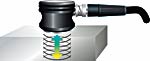
Ultrasonic mechanical vibrations occur at frequencies higher than the limit of human hearing, which is approximately 20 KHz. Most
industrial ultrasonic testing is performed at frequencies between 500 KHz and 20 MHz, although frequencies down to 50 KHz and up to 200 MHz are used in some
specialized situations. In general, NDT using higher frequencies will create a clearer resolution of thin materials or small flaws, and lower frequencies offer better
penetration for measurement of thick samples or materials that transmit sound waves inefficiently. These high-frequency sound waves are generated and received
by ultrasonic transducers, devices that convert electrical energy into mechanical vibrations and vice versa. Transducers used in NDT are low-power devices and
shouldn't be confused with ultrasonic welders or homogenizers, which also use sound waves but at much more powerful levels. There are no known safety hazards associated with ultrasonic NDT. Ultrasonic sound waves are highly directional. Unlike audible sound, which radiates from its source in all directions, ultrasound can be generated as sharply focused
beams that travel in predictable patterns through test material. All sound waves reflect off boundaries between different materials. But at ultrasonic frequencies, the
very short wavelengths permit reflection from very small targets, such as small flaws. An air boundary, like the far wall of a test piece or a crack within an
otherwise solid object, will reflect nearly 100 percent of an ultrasonic sound beam that strikes it. Along with its nondestructive nature, these properties are what make
ultrasound so useful in NDT. Test applications and associated instruments for ultrasonic NDT fall into four
general categories: thickness gages, flaw detectors, imaging systems and material analysis systems.
Thickness gages Ultrasonic thickness gages work by tracking the time
it takes for an ultra-sonic pulse to reflect off the far side of a test piece. Such measurements require access to only one side of the part; thus, there's no
need to cut parts (like you might when using a micrometer or caliper) in order to measure an interior surface that's difficult or impossible to reach. Most
engineering materials, such as metals, plastics, ceramics, composites, epoxies and glass, lend themselves to ultrasonic thickness gaging. Liquid
levels and biological samples can also be measured. Online or in-process measuring of extruded plastic, rolled metal and similar materials is possible, as is measuring coatings on substrates
and individual layers of multilayer parts. Materials generally not appropriate for conventional ultrasonic gaging include foam, paper, wood and concrete, although
some highly specialized instruments are available for the latter two. Because ultrasonic sound travels inefficiently through air, a drop of liquid
couplant--typically glycerin, propylene glycol, water or oil--is placed between the transducer and the test piece at the point of measurement. Pulsed ultrasound
generated by the transducer enters the test piece, travels through it to the far wall and reflects back to the transducer. In a manner similar to radar or sonar, the gage
precisely measures the time interval between the initial pulse and the echo from the far wall, which is typically only a few microseconds. The gage will also apply a
small adjustment, called a zero offset, to compensate for delay times in the instrument and probe. The gage divides the round-trip pulse transit time by two to
obtain the one-way transit time and then multiplies the one-way transit time by the speed that sound travels through the given test material to calculate the part's thickness.
Sound velocity is an essential part of this calculation. Different materials transmit sound waves at different speeds, and sound velocity in some materials--particularly
plastics--varies with temperature. Thus, it's essential to calibrate an ultrasonic gage with the correct sound velocity for the material being tested, a process that requires
consulting a reference standard of known thicknesses. For any ultrasonic gaging application, the choice of gage and transducer depends
on the test material, the thickness range covered and the accuracy required. Part geometry, temperature and any other special circumstances must be considered.
Commercial ultrasonic gages, however, are generally divided into only two categories: corrosion gages and precision gages.
Perhaps the most important application for ultrasonic gaging is measuring the remaining wall thickness of metal pipes, tanks, structural parts or pressure vessels
subject to internal corrosion. Accordingly, numerous instruments optimized for this type of measurement exist. These "corrosion" gages employ a special type of probe
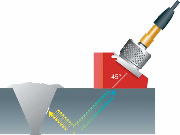
known as a dual-element transducer, which uses separate transmitter and receiver elements angled toward each other to create a V-shaped sound path in the test material.
Angle-Beam Transducer Pulse Reflecting Off A Weld |
Measuring smooth materials with dual-element transducers isn't quite as accurate (typically, accuracy ranges between � 0.004 in. or 0.1 mm) as with some other types of
testing, but they perform significantly better on the rough, pitted surfaces often found in corrosion-survey applications. Many transducers in this class are designed for use on
high-temperature surfaces up to approximately 1,000� C or 500� F, permitting in-service measuring of hot pipes and tanks. Corrosion gages also use signal-processing techniques optimized
for measuring minimum remaining wall thickness in cases of an uneven inside surface on a test piece.
Precision gages, on the other hand, are designed for use on everything else (i.e., noncorroded metal, plastic, glass or ceramics). Measurement accuracy still depends
on material conditions, but in optimum situations, accuracies of � 0.0001 in. or 0.003 mm are possible and accuracies of � 0.001 in. or 0.025 mm are typical.
Common applications for precision gages include measuring molded and extruded plastic parts, machined or cast metal parts, glass bottles and bulbs, plastic cable
jackets, rubber tubing, fiberglass and composite layups, and ceramic parts. Most gage technicians employ hand-held contact transducers, but complex geometries
and online testing require noncontact probes that focus a sound beam through a water column or bath. Many contemporary ultrasonic gages include sophisticated data logging and
transmission capabilities for interfacing with computer databases. Thousands of readings and location codes can be acquired in the field or plant and downloaded to
a PC for recording and statistical analysis. Some hand-held instruments also provide an ultrasonic waveform display that a trained operator can use to verify the validity
of readings in difficult applications and to adjust instrument setup parameters as required to optimize performance.
Flaw detectors Using the same sound reflection principles, ultrasonic
flaw detectors look for echoes that result from cracks, voids or other discontinuities in a test piece. An ultrasonic pulse will travel through solid, homogeneous
material--such as a steel beam or a boiler tube--until it encounters a boundary with a different material--for example, a crack or the test piece's far wall. Flaw
detectors display information on the echo's amplitude and position that can be used to reliably identify and categorize flaws. By viewing the echo pattern from a
reference part and then looking for differences in the patterns received from test pieces, a trained operator can locate hidden flaws before they become a problem.
Weld inspection is the most important application for ultrasonic flaw detectors. Most contemporary digital instruments feature software designed for plotting sound
paths through welds and characterizing any suspect areas. Flaw detectors are also widely used for steam-boiler and pressure-vessel qualification, structural-steel
fabrication, automobile assembly and aircraft maintenance. Although most flaw-detection applications involve metals, the technique can also work effectively
on plastics, composites and ceramics. Modern battery-powered instruments are completely portable and offer full on-board data storage and sophisticated signal processing capability.
Figure 1 Figure 2
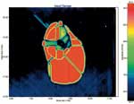
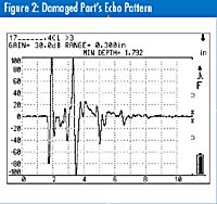 Figure 3: Damaged Part's Ultrasonic Image
|
Using flaw detectors reliably requires a trained operator to set up tests and interpret results. The American Society for Nondestructive Testing has established a
standard for training, Recommended Practice SNT-TC-1A. Typically, a 40-hour classroom course is required for level-one proficiency, and another 40 hours for the
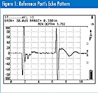
more advanced level-two certification. Figures 1 and 2 illustrate how a typical test might be set up on a fiber-epoxy-composite panel used in an aerospace application.
Figure 1 shows the echo pattern from the part's unflawed area, with the two large echoes representing reflections from the front and back surfaces. Figure 2 depicts
the pattern from an area that's been damaged by impact. This echo arrives more quickly because it represents a reflection from an internal delamination. In this type
of test, the operator establishes that the pattern seen in Figure 1 represents undamaged material and then looks for changes in that pattern; any change represents a difference in the part's
condition at that point. Imaging systems Ultrasonic imaging systems use sharply
focused sound beams to produce pictures--similar to X-rays--that show a test piece's internal structure. To do this, one or more transducers are scanned over the
piece, taking reflection or transmission data at many points and assembling the information into a picture. Changes in echo
position or amplitude will correspond to changes in the part. By mapping these changes it's possible to generate a very detailed image.
Acoustic imaging systems range from small bench-top configurations that generate highly magnified images of small targets, such as the bonds inside integrated
circuits, to heavy-duty systems that fill a large room. The latter are often used for big parts such as aircraft subassemblies.
Figure 3 depicts an ultrasonic image of the same composite panel that appears in figures 1 and 2 with a flaw detector. The extent of the internal damage is clearly
visible as the red area in the panel's center. Material analysis
As the physical structure of a material changes, so will the way sound waves that pass through it. Ultrasonic material analysis generally involves looking at parameters,
such as sound speed, sound attenuation or scattering and frequency content of echoes. These parameters help to analyze or qualify material properties, including an
elastic modulus, density, grain structure, crystal orientation or polymerization patterns. Equipment for these operations can range from simple pulsers or receivers
to complex analysis systems that employ interpretive software. Because sound-transmission properties of different materials vary, ultrasonic
material analysis is a comparative process. Generally, a test is set up using reference standards representing the range of conditions to be quantified. Once test results are
obtained from these references, they can serve to establish the properties of other, similar parts or batches. The exception to this rule is elastic modulus measurement,
in which modulus is calculated directly from two types of wave velocity (i.e., longitudinal and shear) and density.
For further reference This article offers only a brief introduction to the theory and practice of ultrasonic
NDT. For more information, a number of Internet resources are available. Three recommended sites for general information belong to the American Society for Nondestructive Testing ( www.asnt.org ), NDT Net ( www.ndt.net ) and the Iowa State University Center for Nondestructive Testing ( www.cnde.iastate.edu/ncce/UT_CC/Intro_Adv.html ). Additionally, many
manufacturers of ultrasonic test equipment provide theory and applications information on their Web sites.
About the author Tom Nelligan has worked in the field of ultrasonic NDT since 1978. He is a senior
applications engineer and manager of the NDT Applications Lab for Panametrics Inc., in Waltham, Massachusetts. E-mail him at tnelligan@qualitydigest.com .
|