A gaging primer for the rest of us___________________ by George Schuetz
If you keep up with the trade magazines, you might feel left behind reading about all those other shops that have equipped
themselves with the latest precision CMMs, multi-parameter surface measurement systems, vision measurement capabilities and so on. These systems can be invaluable, particularly when there are
unique or high-volume measurement requirements. For a majority of job shop and tool room applications, however, you still can't beat the speed and flexibility of precision hand tools that
generally cost less than a few hundred dollars rather than tens or hundreds of thousands. Precision hand tools perform the same vital functions as their more specialized and
expensive cousins: assuring dimensional accuracy of manufactured components, reducing scrap, monitoring tooling and fixtures for wear and misalignment, and generally keeping manufacturing
processes in control. Rather than relying on a computer to lead operators through all of the measurement steps, hand tools require that the users themselves provide a lot more of the intelligence
necessary for their proper use and care--an important difference and responsibility. Shops with operators who have been given the responsibility of using hand measurement tools
to monitor quality typically turn out more work with fewer rejects. In other words, they're more profitable. The following is a review of simple measurement tools and procedures that shops can
use to tighten up on quality assurance and realize their full profitability. For the rest of us, it's an all-important primer. Chart it
We sure love our computers, and they're proliferating on the shop floor at an ever-increasing pace. However, before you break out the Pentium III system with the
100-gig hard drive, you might consider right-sizing your inspection process with the original shop floor "computer"--a grease pencil and a sheet of poster board. Unnecessary complexity
just increases cost; inspection techniques should be as simple as possible. In many cases, a basic inspection chart is sufficient. The chart defines a process for verifying the initial quality
and proposes a plan for continued process monitoring using simple measurement tools and procedures. The basic inspection chart, however, does not predict when parts might
become bad. This is where statistical process control comes in. Recording measured data on charts and plotting it against time makes it possible to predict when parts will drift out of tolerance
so that corrective action can be taken before this happens. However, in small and medium shops where part volumes are low, process stability is often not an issue. Choose the right tool In spite of what you may have read, the vast majority of machine tools are used to produce parts with
tolerances well within the capabilities of hand tools found out on the shop floor. But what tools should you use? A bewildering variety is available. Take a simple stamped hole, for example,
which may be visually inspected for presence, checked with a go/no-go plug, inspected for size with hand tools, or 100-percent inspected on an automatic gaging system that checks not only size
but also geometric condition (a pricey alternative for most jobs). Here are some guidelines for making the best-balanced choice:   Fixed gage/plug gage--A good choice for checking holes is a fixed gage such as a go/no-go plug gage. Inexpensive, simple and easy-to-use, fixed gaging provides fast,
positive (yes or no) dimensional information that rarely calls for human judgment. Portable and independent of power, they can be
used anywhere in the shop without supporting equipment. For a manufacturing process producing multiple holes at very loose tolerance, this size verification method can be ideal. Fixed gage/plug gage--A good choice for checking holes is a fixed gage such as a go/no-go plug gage. Inexpensive, simple and easy-to-use, fixed gaging provides fast,
positive (yes or no) dimensional information that rarely calls for human judgment. Portable and independent of power, they can be
used anywhere in the shop without supporting equipment. For a manufacturing process producing multiple holes at very loose tolerance, this size verification method can be ideal.
Variable gage/micrometer
--Fixed gaging won't tell you how a measurement characteristic is varying from part to part. For this type of information, you need a hand
tool with a variable readout. While they provide much more information, tools with variable readouts require a certain level of understanding and skill on the part of the users.
Micrometers are the most commonly used variable-reading hand tools for checking lengths and outside diameters on the shop floor. They can also be used for checking
gear threads, depths and grooves. The most common type incorporates two basic scales: the linear scale, which measures directly the axial advancement of the spindle
(usually identical to the pitch of the micrometer screw), and the circumferential (vernier) scale, which indicates the amount of partial rotation appli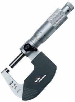 ed to the barrel. ed to the barrel. The micrometer is a contact instrument.
Sufficient torque must be applied to the micrometer to make good positive contact between the part and the instrument. The only torque calibration in the human hand is
the operator's "feel." What feels like solid contact to one operator may not feel correct to another, so the readings will be different. To eliminate the "feel" aspect of
the measurement, micrometer designers incorporate a ratchet or friction thimble mechanism as an attempt to ensure more consistent contact pressure and eliminate
the human influence, achieving more consistent gaging pressure.
Indicating micrometer--An even better solution to the problem of feel is the indicating micrometer, which combines flexibility of range with the high resolution
and consistent gaging force of a dial indicator. The lower anvil of an indicating micrometer is actually the sensitive contact of
a built-in indicator that provides readings (typically in 1 �m/50 � in. gradations) clearly and quickly, with no vernier to read. Like the standard micrometer, you can adjust the
spindle to the size needed and obtain a consistent gaging force when the dial indicator is set to zero using a master. Then the spindle is locked into position. A retraction lever
makes it easy to position the part for measurement and helps reduce wear on the contacts. Now the measuring tool begins to function like a gage, making measurements in a comparative mode. With this one gage an experienced operator can quickly set up the measurement process. Once the gage is locked in place, the indicating micrometer applies identical
gaging pressure for each measurement, regardless of the force applied by the user. An indicating micrometer is perfect for medium-run, high-tolerance parts. Caliper--While micrometers are more accurate, they have a limited measurement
range, usually to 25 mm/1 in. The caliper, on the other hand, will typically measure 0�150 mm/6 in., but can span to 2,000 mm/80 in., depending on the length of the scale.
External measurements are made by closing the jaws over the piece to be measured, and internal measurements are made by opening up the inside diameter contacts.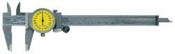 Three different caliper types might be found in a machinist's tool chest. The
vernier caliper, the original design, is the most rugged. Graduated much like a micrometer, it requires the alignment of an
etched scale on the vernier plate with an equally spaced scale running the length of the tool's handle. Skillful tool alignment and interpretation is necessary to achieve the stated accuracy. Similar in construction to the vernier caliper, the dial caliper replaces the vernier scale with a dial indicator. The indicator is fixed to the moveable jaw and engaged with a
toothed rack on the body of the unit. The dial, which is typically balanced (i.e., can move in either plus or minus directions from zero), may be graduated in either inch or
metric units. The dial caliper is a dual-purpose tool for making either direct or comparative measurements. Another useful feature of the dial caliper are jaws that slide
past each other to allow contact points or depth rod extensions to fit into narrow openings for small ID measurements.
In the last 20 years, numerous electronic features have been developed to make digital calipers easier to use without adding substantial cost. These include easy switching
between inch and metric units, tolerance indications, digital output to electronic data collection systems, zero setting anywhere along the caliper's range, and retention of the
zero setting even when the caliper is turned off. With no moving parts in the readout, digital calipers are exceptionally durable.
Use it right Measurement results are limited by the condition of the gage and the manner in which it
is used. Adhere to the following guidelines and you can expect good results: Care and respect--All hand tools must be treated with care and respect. Don't use
them for other purposes (such as prying things apart or hammering things together). Wipe the tools clean after using, and don't throw them on the workbench. For dial
calipers, be particularly wary of dirt, which can accumulate on the rack, throwing measurements off and ultimately damaging the indicator. Store a tool in its case. If it's
going to be there for a while, apply a thin coat of oil to the jaws to inhibit corrosion. Wear--Check the tools often for wear, as well as burrs and scratches on the jaws
and contacting surfaces. In the case of a caliper, a simple way to do this is to pass a master disc along the jaws while inspecting for wear or taper. Calibration--All measurement tools need to be calibrated at least once a year, more
often with heavy use or multiple users. Fixed gages are sent to a calibration room where the plug or ring is measured for size and compared to a tolerance specified by the gage's
classification. It can also be measured at multiple locations to inspect for form errors and will be visually inspected for scratches and nicks. Gage resolution--Before you pick up a tool to measure a part, make sure it has the
resolution you need. The rule of 10 says that a measurement tool should have 10 times more resolution than the tolerance of the dimension. Calipers typically read in 0.001 in.
or 0.0001 in. units, so if the tolerance is tighter than 0.0005 in., a higher-accuracy gage is needed. 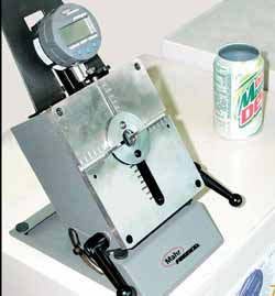 "Feel"--Positioning hand measurement tools and interpreting the measurement results require skill. As users develop their "feel" for the tool, measurement
results become more consistent. Although the addition of digital readouts may remove some of the guesswork, applying the tool properly will still require
skill. Find some time to practice with all of your measurement tools. "Feel"--Positioning hand measurement tools and interpreting the measurement results require skill. As users develop their "feel" for the tool, measurement
results become more consistent. Although the addition of digital readouts may remove some of the guesswork, applying the tool properly will still require
skill. Find some time to practice with all of your measurement tools.
Special tooling--Some parts will require special tooling to ensure that the critical dimensions can be measured quickly and reliably. A good example is
the metal-forming process used to manufacture aluminum cans: Trying to hold a can and measure it is self-defeating because the can distorts. One solution is
tooling a fixture to "round up" the part for diameter measurement. Remember the 80/20 rule
The 80/20 rule is an amazingly universal guideline that predicts 80 percent of your best results will come from 20 percent of the potential sources. (For example, 80 percent of
most companies' sales come from about 20 percent of their customers). As such, it makes really good sense to treat that small percentage well.
By the same token, most of the measurement results vital to quality assurance in tool rooms and job shops are generated by a very small number of hand tools--those
discussed in this article. So it's equally sensible to know how to apply these tools, take care of them and use them well. As the 80/20 rule implies, the payback your shop
realizes in terms of reduced costs will greatly exceed the small investment of time necessary to become proficient with simple hand tools. About the author George Schuetz is director of precision gages at Mahr Federal Inc. E-mail him at gschuetz@qualitydigest.com . |