| by Dirk Dusharme
Even with all the advancements in noncontact 3-D measurement technologies and the ability to accurately measure into the submicron range, there's still a need for contact probing. Although optical or laser-based systems can quickly measure small visible features, they can't as yet measure into deep narrow holes or peek around feature edges such as undercuts. This is where touch probes are still the technology of choice
Within the realm of 3-D micromeasurement has grown a class of measurement systems using multisensor technology, usually some combination of optical, laser and contact measurement. The goal with these machines is to provide an efficient means to measure visible features of relatively large objects, and at the same time have the capability to locate and measure hidden features in the well-below 100-micron range--often with submicron accuracy.
|
You might be interested in just how much force a microNewton (µN) represents. For the purposes of illustration we can consider a Newton as a measure of weight—at least on Earth at sea level, otherwise all comparisons are off—where one Newton is roughly equal to 100 grams, or about the weight of a large plum… or if you’re from my boss’s neck of the woods, a Bruegger’s bagel. A microNewton (µN) is, therefore, about equal to 100 micrograms, or a bit more than a single grain of salt. So get out your magnifying glass, carefully pick a single large grain of salt (about 1/250 of an inch across) off your bagel and place it onto the back of your hand. Feel that weight sitting there? No? Well, that’s one µN.
|
Although optical- and laser-based measurement on multisensor systems provide highly accurate measurement of visible surfaces, it's increasingly difficult for such systems' touch probes to keep up as parts get smaller and more complex. Imagine touch probing the faces of a 400-µm gear where the gear spacing is only about 25 µm, or measuring the inside diameter and surface roughness of a 1-mm-deep diesel injector orifice that measures only 200 µm in diameter. It doesn't stop there. In the case of injectors, for instance, new guidelines for emission reductions are driving injector technology down to possible 50-µm orifices. At this point, the technological demands of accuracy, contact force, fixturing and, of course, measuring speed are staggering. The growth of microelectromechanical system (MEMS) parts is further taxing the limits of 3-D evaluation.
All that said, several equipment manufacturers are producing multisensor systems that meet the challenge. In this article we'll look at some of these manufacturers and the touch-probe techniques they have developed.
Keep in mind that none of these probes are used in a stand-alone fashion. In each of the following four examples, the touch probes are part of a multisensor system. In such systems, an optical or laser-based probe quickly measures larger features and may then locate the touch probe for critical microprobing that couldn't be done with the noncontact sensor. The data from both sensors are then aligned through the use of software.
The UMAP vision system from Mitutoyo couples a noncontact vision measuring system with an ultrasonically activated probe. The UMAP103 probe is available with a stylus length of either 2 mm or 12 mm, and a diameter as small as 12 µm. The probe tip ball diameter is 30 µm or 80 µm, and is ideally suited for microhole measurement, according to the company.
"Mitutoyo's development of UMAP resulted from a specific request from Toyota Motor Co. for a probing system able to accurately measure the ports on fuel injection system nozzles," says Frank Demski, a Mitutoyo product manager. "Another requirement came from the fiber-optic connector (ferrule) industry. Medical devices, microelectronics, miniature gears and other micromachined parts are just some suitable applications."
Unlike a traditional touch probe that relies upon deflection to trigger a contact, the UMAP103 depends upon the dampening of an ultrasonic field when the probe comes into contact with an object. As shown in figure 1, the UMAP103 normally vibrates at ultrasonic frequencies at a known amplitude, which is measured by the detecting circuit. As the probe comes into contact with the workpiece, the amplitude of the ultrasonic signal decreases. When the signal drops to a predetermined level, the probe is considered to have touched the workpiece. This means that the contact force is very low, generally around 1 µN.
Mitutoyo doesn't have a volumetric accuracy specification for the UMAP103 probe when used with one of the company's vision systems. Mitutoyo does say, however, that when used in the company's ULTRA Quick Vision platforms, linear accuracies of 300 nm (0.3 µm) are possible, with a repeatability of better than 100 nm.
In one application the UMAP was used to measure a 15-25-µm radius on the edge of a piece of plastic to qualify the actual radius without marking the surface of the component. One challenge was that the feature to be measured was equal to or slightly greater than the radius of the stylus. In addition, the positioning of the machine required measurement spacing of 0.5-1 µm to capture the entire edge of the radius.
A part program was created to move and retract the probe normal to the previously measured IJK vector point (a direct line from a contact point that's perpendicular to the surface, where I is used for the length of the vector projected onto the X-axis, J is used for the length of the vector projected onto the Y-axis and K is used for the length of the vector projected onto the Z-axis) to reduce the anticipated cosine error, and measurement points were taken on the flats to allow for a calculation that filtered adjacent point data that was consistent to the two to three previous points (i.e., the X- and Z-axis data was somewhat uniform). This calculation allowed the radius measurement data to use only points that showed variation relative to a radius feature.
Measurement repeatability yielded results in the submicron range for both diameter and circularity.
The F25 CMM from Carl Zeiss IMT is a multisensor CMM that uses what appears to be (with a good magnifying glass) a traditional touch probe for its contact sensor. In this case, however, the stylus for the 3-D microprobe measures only 50-500 µm in diameter and can have a free shaft length of up to 5 mm. The stylus tip can range from 100-700 µm. The stylus itself is mounted on 6.5 × 6.5 mm silicon chip membrane with integrated piezo-resistive elements.
The F25 machine is ideally suited for small parts with demanding tolerance ranges, as well as for those components that feature details difficult to measure due to their small size. "With measurement accuracy in the range of fractions of microns, this machine provides the basis for this high-precision gaging," says Gerrit deGlee, Zeiss's new-products manager. "The F25 optical inspection system, which is fully integrated into the system and software, features superior optical qualities necessary for this type of precision inspection."
Typical applications include implantable medical devices, miniature gears (e.g., in dental equipment), precision miniature watch components from premium watch manufacturers, injection moldings in miniaturized plastics and components for sensor technology.
 The F25's probe construction itself (as seen in figure 2) is a good example of a MEMS part, the type of technology for which Zeiss foresees a strong future market. Roughly speaking, with Zeiss's probe, a microscopically sized flexure is etched into silicon and coated with piezo-resistive material. The necessary conditioning electronics are also on that same quarter-inch-square chip. The stylus attaches to the chip, and the entire probe and electronics are about the size of a pencil eraser. The F25's probe construction itself (as seen in figure 2) is a good example of a MEMS part, the type of technology for which Zeiss foresees a strong future market. Roughly speaking, with Zeiss's probe, a microscopically sized flexure is etched into silicon and coated with piezo-resistive material. The necessary conditioning electronics are also on that same quarter-inch-square chip. The stylus attaches to the chip, and the entire probe and electronics are about the size of a pencil eraser.
"What makes this measuring technology interesting for the future is that this measuring machine permits dimension, form and position measurements on microsystem modules," says Karl Seitz, director of new technologies at Zeiss. "In the future, the F25 may be at the heart of quality assurance for microsystem manufacturers."
Specifications for the F25 with the 3-D microprobe state a volumetric accuracy of 250 nm (0.25 µm) within the machine's almost two-cubic-decimeter measuring envelope (135 × 135 × 100 mm), and a repeatability of 7.5 nm (0.0075 µm). The probe has a contact force of 500 µN.
KERN Microtechnology GmbH & AG, a manufacturer of CNC micromilling machines, is a pilot customer. With the F25, KERN inspects base plates for watches and microinjection moldings with an accuracy of greater than 1 µm.
OGP FeatherProbe
|
The Feather Probe from Optical Gaging Products uses a miniature probe that's in constant micromotion. Similar in appearance to traditional touch probes, the Feather Probe has a small probe tip (as small as 125 µm) at the end of a very narrow stylus. However, the triggering method is very different. As the tip approaches the object to be measured, its micromotion is dampened by the part surface. This threshold-crossing change in the micromotion is registered as a point measurement. Because there's virtually zero deflection, the potential for shanking error that might occur with a touch-trigger probe is eliminated. The measurement technique is sensitive enough (about 10 µN) to allow measurement of very flexible or deformable materials. The technique works equally well in the X, Y and Z axes.
As with other microsensors, an important consideration for the Feather Probe is the overall system accuracy. For example, coordinate measuring machines (CMM) typically offer large measurement volumes. Designed for use with touch-trigger probes, positioning accuracy in such systems may not be as critical as it is for video measuring systems. The CMM merely has to get the probe close enough for the trigger mechanism to register a measurement. Video measuring systems, on the other hand, have the high-resolution positioning necessary for high-magnification imaging of specific part locations within the measurement volume. These measuring systems are consistent with the high lateral and height-measuring capabilities of microsensors. In other words, microprobing is most accurate when the measurement system on which it is done can deliver specific measurement performance. Video measurement systems, such as those from OGP, have this level of precision.
OGP offers the Feather Probe for its Smartscope Flash or SmartScope Quest products. These systems, equipped with the Feather Probe, excel at inspecting the small bores, channels and orifices of parts manufactured using electric discharge machining.
"Many times these customers not only want to know about dimensions at the top of the feature, which can be measured quickly and accurately with video, they need to know about the walls of the bore or channel," explains Bill Gilman, vice president North American sales for OGP. "This requires some type of probing of that vertical surface. This is where Feather Probe excels."
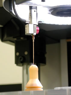
The Werth Fiber Probe WFP 3D has been around for several years but still boasts the smallest probe size--down to 12.5 µm. The spherical glass tip is mounted on the end of a fiber-optic shank that is offered in sizes from 20-200 mm (about 8 in.) long. The length of the shank is limited only by the focal length of the measuring camera.
The probe tip is monitored by a camera. (See figure 3.) The fiber-optic shank and probe tip are aligned near the center axis of the lens. The camera detects the probe tip's deflection as it comes into contact with the work piece, thus indicating a contact. Because of the flexibility and extremely light weight of the probe, the contact force can be as little as 1 µN. Although the fiber-optic shank is relatively flexible, it's rigid enough that the probe always returns to the same at-rest position after it's been deflected.
Because the probe tip must be visible to the camera, illumination is required. The methods of illumination are either a transmitted light mode, where the probe and workpiece are both visible between the light source and the camera, or in a self-illumination mode. In that mode, the fiber-optic shank is illuminated on one end by an LED, and the light is transmitted through the fiber-optic cable to the probe tip.
The Fiber Probe can be used in single point or scanning modes. In scanning mode, it's also capable of surface roughness measurements.
Werth specifies that the Fiber Probe, when used on a Werth Video-Check HA CMM, has a volumetric accuracy of 1.5 µm over a 300-mm diagonal.
One application for the Fiber Probe is the inspection of spray holes in diesel fuel injection nozzles. Typical diameters for these holes are around 200 µm, or about 0.008 in. The depth of the holes is approximately 1 mm (0.040 in.). Because the direction that the diesel fuel sprays is vital, the holes must be measured not only at the face for diameter but at several positions along the length of the hole to determine each hole's angle.
Because the spray holes are dispersed radially and have axial orientation angles ranging from 20º to 45º, they must be inspected on a five-axis machine with a rotary tilt table. After aligning the part by measuring the outer diameter in several places to establish the central axis and zero reference point, the spray holes are first located optically by positioning to their nominal values. Accurate optical measurement of the actual hole position is crucial to get the Fiber Probe into the tiny hole. WinWerth software uses the measured optical values to position the Fiber Probe within the fully automated program. The Fiber Probe is then used to measure several circle diameters at various depths. Constructing a line by connecting the center points of the circles and calculating its orientation relative to the part's central axis yields the spray angle of the diesel fuel hole as well as extremely accurate diameter measurements.
A recent test on a customer's part at Werth's facility showed the difference between the highest and lowest measurement of a feature--over 25 measurements--to be in the order of 0.03 of a degree for the angles and around 0.2 µm for the diameters.
As electronic devices continue to shrink, so do the components embedded within them. Imagine a 4-GB hard drive smaller than a book of matches with all the requisite mechanical parts--read/write head, actuators, spindle, etc.--or ongoing experimentation with 50-µm fuel injector orifices. Probing technology must be prepared to measure these parts, and multisensor measurement system manufacturers such as those mentioned in this article must stay ahead of the curve.
"History is showing that as time progresses, the demand for manufacturing precision is increasing, which requires that the gaging variability decreases," deGlee points out. "Only companies that invest in the research and development of new technology to address this evolution will be able to provide products to answer the industrial requirements."
Dirk Dusharme is Quality Digest's editor in chief.
|