by Dirk Dusharme
In the endless push for high-volume, low-error-rate lean manufacturing, companies are continually looking for measurement equipment that will accurately verify product dimensions without having to remove the product from the manufacturing floor. Additionally, automotive and aerospace manufacturers are looking for fast, accurate means to align subassemblies. Add to this the need to reverse engineer aging molds and dies, many of which were hand-tooled, and it's easy to see the importance of portable 3-D metrology.
In the past, shop floor 3-D measurement simply wasn't accurate enough for many applications, and in some cases it still isn't. However, many advances in the past decade have greatly increased the accuracy of portable 3-D measurement devices for use on the shop floor, and the move is on to integrate this equipment into the manufacturing process.
Although a variety of portable 3-D devices have been largely embraced by aerospace manufacturers for many years, particularly for subassembly alignment, some of the newer 3-D technologies have been slow to catch on with the automotive industry.
The Morgan Motor Co.
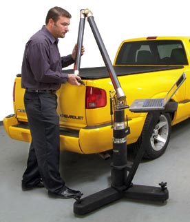
The Morgan Motor Co., based in the small town of Malvern Link in Worcestershire, United Kingdom, is a specialty company that builds 500 custom sports cars every year. The company was founded by H.F.S. Morgan, who began manufacturing automobiles in 1909. The cars are built by a workforce of fewer than 100 employees who lovingly produce these ash-framed vehicles. Due to increased demands from Europe and the United States, Morgan has recently introduced the FaroArm (seen below) to improve build accuracy and thus ease of production.
"The FaroArm has given us the ability to overcome previous accuracy issues and has allowed us to capture data as a design and production aid," says design engineer Derek Jones. "By obtaining accurate data you can reduce production times."
This is an important issue for the company; as its production increases, Morgan needs to become more efficient. "The FaroArm is extremely flexible," says Morgan design engineer Graham Chapman. "It can be moved into different areas within the facility and isn't in one fixed position, so you can also take it to the vehicle rather than vice-versa."
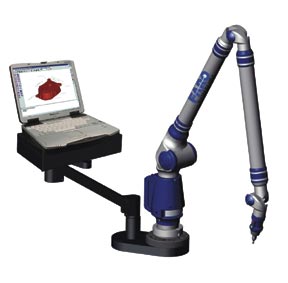
Platinum FaroArm Control Station |
This article is the first of two that will highlight a variety of shop floor 3-D technologies and some of their applications in an automotive environment. Most, if not all, of the products mentioned here will also be shown at the Coordinate Metrology Systems Conference in Orlando, Florida, from July 17-21, 2006. The CMSC is the only show to focus strictly on portable 3-D metrology hardware, software and applications.
In the following pages we will introduce technologies that you may not be familiar with. In so doing we are obviously highlighting the benefits of each technology. Because the benefit or usefulness of any technology is largely dependent on its application and environment, you should arrange to have equipment tested in your own environment to determine its applicability.
The most recognizable of portable 3-D measurement devices are the articulating arm coordinate measuring machines (CMM) manufactured by such companies as FARO Technologies Inc. and Romer Inc. (a Hexagon Metrology company).
These are manually operated instruments consisting of an up to 7 ft "arm" (a roughly 14 ft measuring envelope) that pivots at the wrist, elbow, shoulder and base, allowing a probe or laser scanner at the end of the arm to reach almost anywhere on the part being measured. Encoders at the pivot points report the angle of each joint and thus the location of the probe tip in 3-D space. The entire arm and base can be easily moved to anywhere on the shop floor and set up in minutes. It's also possible to position the entire instrument at multiple locations (i.e., "leap-frog") around a very large part and stitch together the data collected from multiple setups to extend the measurement volume.
A disadvantage of arms is that they require an operator to move the probe to each location on the part to take a measurement.
The accuracy of arms has increased tremendously over the years. The most accurate FaroArm has a published single-point accuracy of 5 µm; Romer's will measure to 4 µm in the single-point sphere test.
Two automobiles built in General Motors Corp.'s assembly operations in Lansing, Michigan, currently rank first and third in the Global Delivery Survey, a crucial quality audit. The rankings are especially impressive because the cars--the Pontiac Grand Am and Oldsmobile Alero--have achieved this distinction in their first year of production at Lansing. The GDS benchmark is the rigorous final evaluation that every GM car gets from independent quality assurance teams.
"We attribute a portion of the GDS audit success to the extremely good body fits on the Grand Am and the Alero," says plant manager Jim Zubkus. "The portable CMM allows us to qualify the tooling in the body-weld-assembly systems better then ever before."
A Romer portable CMM frees Lansing's dimensional integrity team--the engineers and skilled tradespeople responsible for the fit of the body sheet metal--from the tedious guesswork of indirect measurement. The teams are no longer shackled to the traditional stationary CMM--huge and accurate but slow and expensive.
"Before, we verified the tools by carrying sample panels or subassemblies to the CMM room and measuring the product," Zubkus explains. "Now we measure the tools right where they sit in the production system.
Integrated Wi-Fi adds to the portability of Romer's INFINITE series CMM.
|
"It doesn't matter if the CMM room is just three feet away from the line" he adds. "By the time you get the measurements back it may be two days. Even if it's only two hours, dozens of cars have been built which may have a dimensional discrepancy. All of them have to be chased down, inspected and fixed."
Commercially available laser trackers have been around since the 1980s. The basic operation is simple. A laser beam is aimed, usually at a hand-held retroreflector, which bounces the beam back to the tracker. The laser's time of flight gives the distance to the reflector, while encoders on the tracker head provide the azimuth and elevation--thus determining the retroreflector's and point of interest's 3-D location. As the reflector is moved around the part, the laser "tracks" it. The operator triggers the tracker to collect point data wherever desired. (Although somewhat dated, a good description of the technology can be found at www.qualitydigest.com/feb98/html/lasertrk.html.)
As with the articulating arm, the laser tracker is a manual measurement device requiring an operator to move a retro-reflector around the part being measured.
Key players in the laser tracker market are API, FARO (which purchased SMX), and Leica Geosystems (whose tracker engine is licensed from API).
Accuracies are on a par with articulating arms when working within the same envelope. API's product, for instance, has an accuracy of about 25 µm at 16 ft and can measure objects up to 400 ft away. Leica's laser tracker can measure objects with a measuring volume of up to 131 ft in diameter with an accuracy of +/-10 µm/m, at a measuring rate of up to 3,000 points per second. As these specs illustrate, the advantage of laser trackers is that they can measure very large objects, although the accuracy diminishes as the measuring envelope increases.
In practical terms, laser trackers are often used for accurate 3-D measurement at close range and for subassembly alignment of larger objects at a greater range.
Leica's "Walk Around" armless and wireless Leica T-Probe is a variation on a typical laser tracker. The hand-held T-Probe interacts with the laser tracker in such a way as to allow measurements into holes or features that would normally be out of sight for the tracker's laser. This ability was a key reason BMW chose the Leica LTD800 system. Inspectors were able to measure into recesses and cavities with precision: The length measurement precision is +/- 60 µm (two sigma) in a measuring volume of up to 15 m (49 ft).
Among the BMW team's tasks are analytical measurements and random tests to check production runs for an entire automotive series. It's also important to conduct metrology jobs quickly and efficiently, using the best measuring tool available.
The combination of a laser tracker and probe as a full-fledged CMM with built-in mobility and no need for dedicated space has been proven and tested. According to BMW, this combination holds its ground with three-axis CMMs.
This technology has been around for a long time but has seen a resurgence due to advances in computing power and digital photography. The concept is simple and more than 100 years old. Multiple cameras photograph targets on a part simultaneously--or multiple images are taken with one camera from several angles. Software uses triangulation to determine the relative location of the targets in 3-D space. There must be at least one dimension in the photograph that is known (often a scale bar) to accurately scale the distance between unknown points.
Although not as accurate as articulating arms or laser trackers, this technology can acquire many more points in much less time. Once targets--either retroreflective material attached to a part or spots projected onto the surface--are in place, a single operator can photograph very large areas in a few minutes and capture thousands of points. Although this is still largely a manual operation, more points can be taken per unit of time than with the previously discussed technologies.
Because the targets and scale bar are part of the image and all points are acquired simultaneously, part or measurement system movement isn't an issue; this isn't true with arms or trackers. Additionally, multiple images can be stitched together to give a complete view of the entire object.
One photogrammetry system especially tailored for large-scale assembly operations is produced by Geodetic Systems Inc. (See the article "Sky's the Limit" in our May 2006 issue.) This system uses multiple cameras and/or multiple positions to image the part to be measured. As with trackers, the accuracy is dependent, among other elements, on the field of view (itself dictated by the distance to the target). When measuring within a 15 ft field of view, Geodetic's system has an accuracy of 25-50 µm. Although widely used in aerospace, GSI products are now beginning to appear in automotive environments as well.
Capture 3D and Aicon also produce photogrammetry systems using a standard digital camera; however, their main thrust is structured white-light scanning systems.
If you have been to any metrology show within the past decade, you have seen portable laser scanners such as those sold by LDI, Leica, Perceptron and others. These devices are hand-held or mounted on an articulating arm, and a laser is used to scan the area of interest. Sensors in the scanner detect how the beam deforms around the object, and these data are used to create a point cloud. By tying these data into an existing coordinate system established by another measurement device, such as a laser tracker or an articulating arm, individual scans can be stitched together to form a high-density point cloud of large objects.
White-light scanners are similar to laser scanners but use a different technique and capture more points in a shorter period of time. Rather than a single laser line scanned across a part, structured white-light scanning employs two cameras separated by a known distance and a pattern projector that projects a series of lines or grids onto the part. The cameras triangulate on the pattern. Because the pattern distorts as it's projected on a curved surface, a part's contours can be determined. Millions of 3-D points are captured in just a few seconds, generating a very complete point cloud of the object.
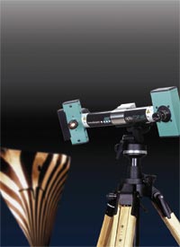 Breuckmann's optoTOP-HE projects and measures a fringe pattern on the object at left.
 |
As with photogrammetry, concerns about part or fixture movement are reduced because entire areas are imaged at once and targets on the part or fixture determine the local coordinate system. Along with the relatively small size of structured white-light systems, this leads to a great advantage: automation.
In the previously discussed technologies, we noted that a certain amount of manual intervention is required. Structured white-light systems, on the other hand, can be mounted on robots or other motion-control systems, allowing automated part inspection. In that particular case, a rotating fixture (or robot arm) holds the part to be measured. Targets on the fixture are used as reference points. The part is rotated in front of the scanner, or the scanner is moved around the part.
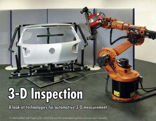
Capture 3D and Accurex Dimensional Measurement are two structured white-light vendors that will appear at this year's CMSC show. Capture 3D utilizes the Advanced Topometric Optical Sensor (ATOS) scanner manufactured by GOM mbH in Germany for its 3-D shop floor solutions. Accurex provides systems produced by Breuckmann GmbH, also located in Germany.
Both systems claim accuracies down to about 15 µm, although accuracies are dependent on lenses and distance from the part. One Capture 3D customer reports having achieved 75 µm accuracy over a 23 × 2 × 2 ft volume.
For the digitization of the interior of a Ford Focus, markers were placed on all parts that needed to be digitized, and Capture 3D's ATOS XL system was used to measure the 3-D positions of the visible markers and transform them into the coordinate system of the car. Elements that could be easily removed, such as seats, were put outside the car and digitized separately. The markers ensured that the coordinates of the removed components could be transformed correctly into the car's coordinate system.
The ATOS sensor was calibrated to a typical measuring area of 350 × 280 mm, with a short working distance to provide access to all needed views. For some details, the lenses were exchanged and the system calibrated for a 200 × 160 mm or a 100 × 80 mm working area. (Areas as large as 2 × 2 m are possible.) The interior of the car was digitized in two days, including the floor, ceiling, dashboard and seats.
In an additional day, the complete data from the car were recomputed by the ATOS software into an STL file. Using these data, milling or modeling on STL data or reverse-engineering jobs can be started. In addition, it's simple to duplicate the measured part using rapid prototyping systems.
Although structured light scanners are typically used to measure parts, automakers have used them to measure much larger surfaces. High-resolution data from road surfaces, for instance, are required in simulation calculations for the development of automobile suspension systems to provide maximum comfort and durability.
Automobile and tire manufacturers use these data for computer simulation of the interaction between road, tire and chassis, and to provide a better understanding of the simulation of chassis mechanisms. Increasing demands are placed on computer simulations to assess the influence of these data on driving comfort and vehicle life. Breuckmann has measured road surfaces and test tracks for all leading European and Japanese car manufacturers. The test tracks are up to 10 km in length, with a width of approximately 4 m and a height variation of several meters.
To measure the tracks, two optoTOP-HE-2500 topometric sensors are mounted on the roof railing of the measuring vehicle and have a total field of view of approximately 4 × 2.5 m. Single images are matched by means of index marks and object geometry, respectively. The total measuring time is up to 150 m per hour, depending on surface geometry and surface texture. The measurement method stands out due to its high local resolution and precision combined with a high global accuracy. A local resolution of better than 0.5 mm and an accuracy of approximately 1.25 mm can be achieved. By applying a global reference system such as a tachymetry system or GPS, the overall accuracy is better than 10 mm over 5 km.
Keeping Mustangs Rolling
When a stamping die gives out, manufacturing stops--an interruption that major car companies cannot afford.
That was the position Ford found itself in when the steel tools (steels) used for stamping and restriking a Mustang crossmember reached the end of their life cycles. Rather than invest $400 million to retool a Mustang model still on the market, Ford opted to rebuild the tools before they officially fell out of commission. Ford turned to Detail Technologies to reverse engineer two Mustang stamping dies that were nearing the end of their life spans.
"The Mustang tools were not broken," explains John Amos, a reverse-engineering specialist at Detail Technologies. "They could possibly have run another year or two. But the probability of failure and the cost of that failure outweighed the cost of rebuilding a couple of tools."
The two Mustang tools that Ford decided to have rebuilt are used to stamp crossmembers that are about 6 ft long and 8 in. wide. Forty-two individual steels were sent to Detail Technologies--21 per tool--each about the size of a breadbox.
Amos scanned the steels using an LDI RPS450 laser scanner to create a point cloud of the parts. Additional 2-D data were added via touch probing, and the final point cloud was loaded into Geomagic Studio. The resulting surface boundaries were manipulated until Amos had a structure that would create accurate, workable surfaces. The data were saved as an IGES file and loaded into the MasterCam CAD system.
The computer-aided manufacturing (CAM) department used the CAD files to manufacture blocks that were rough-machined, semifinished, heat-treated and hard-milled into identical tool replacements. The finalized tools were in production after a total of five weeks--four days devoted to the scanning and modeling, the rest of the time to taking apart the tools and manufacturing. The tools were out of production for only 10 days.
"So often the reverse-engineering work I do revolves around creating data that a customer can no longer locate," says Amos. "There's generally no downtime available in production tool runs, so when they need it, they need it now. It would be nice if businesses would invest in the security of having a reproducible product up front by scanning tools right after certification. The process would be much more efficient." |
Needless to say, none of this spiffy hardware is of any use without the software to interpret the data. Although all of these systems come bundled with the necessary software for data analysis, there are several companies producing software that will interface to these products and more, in some cases providing more functionality than the bundled software.
Specialty software helps users accomplish several key functions for 3-D metrology. One common use is to help reverse engineer older parts or tools for which there is no CAD file and to create a document that can easily be used by a company's CAD and manufacturing software. In this case, software will interface with a 3-D measurement device to capture a point cloud and convert it into a CAD model. Another use is with inspection, to compare the as-built part to the CAD drawing and identify areas where the part is out of spec. A few of the software companies involved with these types of products include Brunson, Delcam, Geomagic, Metrologic and Verisurf.
A trend in the aerospace industry is also making advances in automotive manufacturing: inspection and digital build directly from a product's CAD model. Processes that are using this approach include part and assembly inspection, periodic tooling inspection, and setup and verification in automated manufacturing cells. To do this effectively, modern software applications that allow direct import of the master CAD model design (Catia model, for example) are used with digital measuring devices such as laser trackers and CMMs.
Although old techniques involved taking manual measurements and comparing them with drafting dimensions, the new process allows direct, live measuring to the CAD model master definition.
Third-party software companies have helped original equipment manufacturers keep up with the new CAD-intensive requirements. Software allows users to read CAD models directly from the native file format, easily connect their 3-D measurement device and measure a part for inspection.
A good example is an application at DaimlerChrysler's Warren stamping plant, which utilizes a Faro tracker with Verisurf software to set and verify part-locating features in an automated welding manufacturing cell. Instead of taking manual measurements and setting to blueprint dimensions, technicians set the part-locating features from the Catia master CAD model of the part. It's important to note that Chrysler utilizes the design of the automobile assembly for this task, not the design of the tooling. This way it maintains full traceability to the digital vehicle definition, eliminating questions that might arise from potential disparities between product design, tool design and other definition mediums such as drawings.
Of the numerous metrology software platforms that are used for digital build and inspection, some are considerably more capable than others when it comes to this technology using model-based definition (MBD). The more advanced systems allow import of geometric dimensioning and tolerancing constraints (termed "FT&A" in Catia V5) and use them directly with the device to inspect the part or tool, or to set features on assembly fixtures.
These are just a smattering of the hardware and software options available for 3-D measurement. Next month we will provide as complete a list as possible of the products and technologies that will be showcased at the CMSC show.
Dirk Dusharme is Quality Digest's editor in chief.
|