by Doug McClure
X-ray inspection of printed circuit boards and other assemblies has become a process requirement for the vast majority of electronics manufacturers. Having X-ray inspection tools can affect electronics manufacturing companies at every level, from the largest original equipment manufacturers (OEM) to the smallest contract manufacturers. Remaining competitive requires compliance to ever-changing quality requirements and standards. Some beneficial reasons for X-ray inspection can include the following:
• Several new package technologies lack alternative test access by other quality inspection methodologies (e.g., ball grid array [BGA] , chip scale packaging
[CSP], Flip-Chip, etc.).
•X-ray inspection can be used to improve process performance and board quality while reducing scrap and the expense of warranty returns, thereby reducing costs throughout the entire product life cycle.
• Every aspect of a delivered product--cost, functionality and customer satisfaction levels--affects future business and bottom-line revenue. Because of these benefits, having X-ray inspection has become a competitive advantage, to the extent that more and more OEMs are strongly favoring or even requiring contract manufacturers and rework facilities to have in-house X-ray inspection capabilities.
Technical note: It’s generally known that manual X-ray inspection is ideal for high-mix, low-volume manufacturing environments. What’s not so commonly understood is that almost any X-ray inspection system, whether it costs $50,000 or $500,000, can recognize fundamental faults such as bridging, missing, voids, insufficient/excess solder and linear misalignments. Therefore, it should be noted that price isn’t always indicative of performance.
During the past decade, practically nothing has occurred in the way of X-ray technology advancements which hasn’t increased system cost and complexity. However, these advancements have provided only nominal benefits.
An example of this would be the myth of nanofocus. Simple physics dictates that if you want to penetrate a dense package or board, you have to drive the tube with more current, thereby eliminating the properties of nanofocus. Technically speaking, the nanofocus spot size grows to microfocus size as the power to penetrate materials of relative density and/or thickness is increased. In addition, essentially all systems are nearly equal in resolution below 40X magnification, regardless of spot size. This is due to the blunting effect of X-rays when distributed across a broader image-detection area relative to object-source distance (OSD) and object-detector distance (ODD).
Many X-ray inspection system and software embellishments are the result of selling features against the competition instead of selling solutions that fit a customer’s needs.
One example of this is 3-D visualization software, some of which can take up to eight minutes or more in rendering a graphic of an X-ray view. It’s a great marketing tool but not very practical. Just ask anyone who owns a system offering this capability how often he or she uses it during an inspection.
Another example could include highly automated, inline and 3-D X-ray inspection systems, especially when used in less-than-ideal applications. These systems carry a hefty price tag (as much as $350,000–$500,000) and aside from the initial cost, require a significant ongoing investment in time and resources to develop and maintain test applications. These are excellent tools when used under ideal circumstances (i.e., high-volume production with very few changes to product design, component sourcing or process).
This begs the question, “Just what’s really necessary, practical and efficient when it comes to manufacturing or rework quality verification?”
To answer this question thoroughly for a broad audience with variable applications will require some basic technology explanations. Following are some key points of interest:
• Sample handling. Perhaps one of the most important and obvious qualifying questions with respect to any test system selection or test application is, “Does it fit?” Sample handling with respect to board size can be broken down into two parts: machine-loadable board size and inspectable board test area. Loadable board size is fairly self-explanatory: Does the board fit into the sample holder of the machine? Inspectable board test area, on the other hand, refers to the percentage of a board that can be viewed and/or tested without rotating the sample. This is often missing or inaccurately stated in many data sheets, Web sites and advertised system specifications. Nonetheless, it’s a notable criterion and will ultimately affect inspection speed.
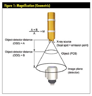
• Magnification and field of view (FOV). Magnification and FOV have opposing correlations. Mathematically speaking, magnification is defined as: Magnification (M) equals OSD plus ODD, divided by ODD, as seen in figure 1 below.
The goal should be to obtain a balance between sufficient magnification (i.e., inspection detail) and sufficient FOV. With high magnification, the FOV becomes smaller, thereby reducing the speed at which a board can be completely inspected. Therefore, throughput and magnification are opposing objectives, and the best balance of each depends upon your application. See figure 2 below for an illustration of this principle.
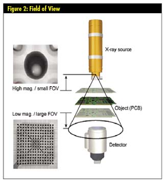
A typical 250 BGA package will require approximately 10X magnification to display full screen, whereas a single ball displayed in full screen will require approximately 350X magnification. Magnification and FOV will vary from machine to machine and are dependent upon how close you can move the sample object to the X-ray emissions point or focal spot relative to the distance to the detector.
• X-ray tubes (open vs. sealed). Tubes may range in power (typically 50 Kv to 160 Kv), orientation (e.g., end-windowed or side-windowed) and resolution (i.e., spot size). There are basically two types: sealed tube and open tube. A sealed-tube X-ray source is one in which the interior components are sealed in a vacuum. A sealed tube can be placed in standby “on” mode and used immediately upon system start-up. Sealed tubes are notable for long service life. However, if a sealed tube fails, it must be returned to the factory for repairs or replaced.
An open-tube X-ray source requires a vacuum to be created by performing a two-stage pumping process every time the system is switched on. Even in standby these systems require some warm-up time before use. The open-tube X-ray source filaments and targets can be replaced on site, but as a rule they require this more often than sealed tubes. It should be noted that X-ray tubes are generally the most expensive component of nearly all X-ray inspection systems. Therefore, whichever system or tube type is selected (and they both have merit), there is no substitute for the proper care and operation of the systems (and a good warranty). Read, know and follow the manufacturer’s recommended operational guidelines because this could save you thousands of dollars.
• Spot size (resolution). Spot size is the size of the electron spot on the face of a tungsten target. This is a function of an X-ray tube’s ability to focus the electron beam, which in turn is a major component of image resolution in all X-ray inspection systems.
Remember the myth of nanofocus? This is where it applies. Because spot size varies in relation to the applied electron beam power, an X-ray tube (nanofocus or microfocus) may be restricted to relatively low-power operation if very high-resolution images are required. Remember that essentially all systems are nearly equal in resolution below 40 × magnification, regardless of spot size.
• X-ray image detectors. In modern X-ray inspection system applications (real-time radiography), the detection of X-ray emissions is accomplished by an image intensifier and camera combination, or flat-panel detectors. Each convert X-rays to electrical signals for visual presentation on a display screen and computer enhancement and/or analysis. Although flat-panel detectors have decreased in cost and increased in performance, they still require more power and longer X-ray integration time than traditional image intensifier and camera methods. Therefore, flat-panel detector systems presently have the disadvantage of high prices and poor power efficiencies. Future technologies in this area bear watching because there is much hope for upcoming improvements.
• Angular board manipulation. This refers to the ability of a sample printed circuit board (PCB) to be rotated within the X-ray imaging path to display oblique (i.e., off-axis) viewing. This is accomplished to reveal electrical solder connection shape, size, faults, etc., which is especially important with double-sided boards where top- and bottom-side components may obscure clear viewing of object details. A rotation angle from 0–40° is ideal for this application. Manual or mechanical board manipulation will influence machine cost and operator convenience but makes little difference to the effectiveness of the inspection.
• Software. For all X-ray systems, image-processing software has a direct effect on speed, accuracy and repeatable analysis results. Typical software packages include basic image-quality enhancement tools such as image-averaging and visual-improvement filters. By way of this collective “image processing,” visual detail is improved, thereby making it easier for an operator to quickly evaluate overall quality and identify subtle anomalies. Other software tools such as data collection, measurement, and analysis reporting provide interactive diagnostics that further isolate, quantify and document faults for corrective action. It should be noted that the minimal tools needed to get the job done are most often used.
Working with a broad variety of X-ray inspection technologies has consistently illustrated that what the user needs are the minimal tools necessary to complete the job quickly, easily and efficiently, regardless of the application.
How often are they used? This varies, but the majority of end-users we’ve spoken with stated that, on average, their inspection systems were only used about eight hours per work week to perform process verification and random quality sampling spot checks. How are they used? In short, pop in a board and fly it around under live X-rays using a large FOV to see as much of the board as possible at one time. Even many of the fully automated systems costing up to $500,000 are being used in this way, which brings us to the “value” proposition.
In today’s capital equipment market, value can be appraised as: Application relevance (i.e., solution) plus performance (i.e., overall application usefulness) vs. cost (i.e., return on investment life-cycle usefulness) equals value. Capital equipment buyers and specifiers alike have become educated, frugal shoppers. This is not as much of a philosophical shift as it is a bottom-line requirement to remain competitively and economically efficient. In short, buy what you need for the right price, while being mindful of operational simplicity to facilitate ease of use and long-term, low-cost ownership.
This situation has caused some X-ray inspection equipment manufacturers to rethink system design and to focus on providing systems that are affordable, of high quality and designed for application usefulness without loading down the system with extras that provide little value.
Doug McClure holds a bachelor’s degree in computer information science from the University of California, San Diego. McClure’s X-ray inspection experience was gained while working for industry leaders such as Four Pi Systems, Hewlett Packard/Agilent, Nicolet Imaging Systems, GenRad, Teradyne and FocalSpot Inc.
FocalSpot designs, manufactures and markets its own line of affordable X-ray inspection systems and distributes
DEN-ON advanced lead-free rework solutions in North and South America, Canada and Mexico.
For more information visit www.focalspot.com
|
