Gathering and analyzing large amounts of dimensional data is the most effective technique for
maintaining control of manufacturing processes. Analysis of this information can indicate out-of-tolerance conditions and suggest ways of modifying the process to improve work-piece quality.
However, accurately collecting enough dimensional information for effective process control has been a challenge, particularly for contoured shapes. Today there are coordinate measuring machines
(CMMs) that automatically measure 3-D forms and use that information in conjunction with computer-aided design (CAD) systems to provide insights into processes involved in the work-piece
manufacturing operation. They are called scanning CMMs. Scanning is simply a way of automatically collecting a large number of data points to accurately define the shape of an object.
Faster data collection Conventional CMMs equipped with touch-trigger probes use the stitch scanning method
to record streams of points from a part surface. In stitch scanning, the CMM lifts the probe head from the surface of the part, moves it slightly forward and lowers it until contact is made again
for every data point that is collected. This single-point procedure is slow and not suitable for efficient measurement of complex shapes. Analog probes for continuous
scanning--designed to send an uninterrupted stream of data back to the system computer--are a solution to this problem because they eliminate the time-wasting auxiliary movements required by
point-to-point measuring probes. CMMs use two different types of continuous scanning methods, depending on whether the geometry of the work piece is defined or undefined.
Open-loop scanning is a high-speed technique used for meas-uring theoretically known (or defined) shapes on parts whose geometry, characterized by having few curves and surfaces, allows the
probe to maintain contact with the surface. The machine motion is controlled by the nominal geometric data recorded in the CMM part program, which records the magnitude of error between the
actual surface and the nominal. Prismatic features such as holes, planes and cylinders can be scanned in a few seconds with high repeatability and accuracy, and a complete description of their
geometry, including dimension, location and form generated. Acquiring a larger number of data points ensures higher repeatability for diameter and position and a much better definition of the
shape of the form features. Closed-loop scanning is a high-accuracy technique particularly useful for digitizing undefined, convoluted shapes. The analog scanning probe detects
changes in the surface directions of the part and adjusts itself to maintain contact with the work piece. Dies and molds--or any part that includes complex, very small and/or 3-D curved surfaces,
such as turbine blades, gears, cams and rotors--are candidates for closed-loop scanning. Probes are the key to accurate scanning
Analog probes act as small, accurate auxiliary three-axis measuring machines whose readings complement those of the CMM. In the scanning process, the probe stylus is in
constant contact with the part surface, and the measuring-machine control system ensures that a consistent gaging force is maintained by detecting any deviations and regulating them immediately.
This force deflects the three probe axes, and high-resolution electronic transducers record the displacement. The dimensional data is continuously read from the machine scales and analog probe
transducers and sent to the software for analysis.
Figure 1: CMM Accuracy
The key in providing a flexible scanning CMM is having very high and repeatable accuracy
over the widest range of probe deflection.Figure 2: Force-Deflection Linearity
The accuracy of a scanning head depends on the linearity of its force-deflection
characteristics. The more extensive this linear range is, the higher the scanning speed. |
The accuracy of the data depends on the linearity of the probe as it reacts to surface changes (i.e., the force it takes to deflect the probe's stylus is proportional to the deflection,
producing the same accuracy over the full range of the deflection). (See figures 1 and 2.) The more extensive the linear range, the better the probe will handle dramatic surface
changes while maintaining high speeds. Studies have indicated that a linear scanning range of �0.1 mm is necessary for a scanning speed of 10 mm/s. If the linear range is
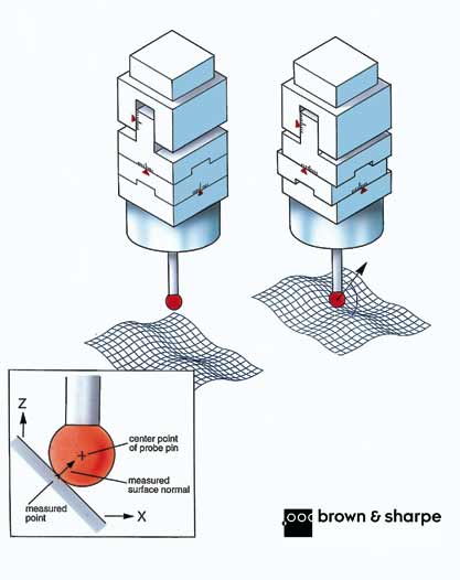
smaller, the speed must be reduced. True 3-D probe systems are "isotropic," meaning that they exert the same probing force in all three measuring axes
simultaneously. Therefore, when the probe tip touches the part surface, it's deflected exactly along a vector that is precisely orthogonal to the part surface at all points (see Figure 3).
The 3-D probe head is capable of precisely and simultaneously meas-uring the X, Y and Z coordinates of the contact point and the local orientation of the work-piece surface (I, J and
K vectors). This feature guarantees the accuracy of the measuring process. In CMMs, scale readings always refer to the center of the probe tip. Its location relative to
the machine coordinate system is defined through a probe calibration cycle executed prior to measuring. The purpose of the calibration cycle is to determine exactly the
center and radius of the probe tip in use. Once these values are known, the software mathematically offsets the coordinates by the
radius of the tip during the measuring operation. The vector normal to the probed surface at the point of contact determines the direction of this offset. With a 3-D
probe, the direction of this vector is automatically determined on the basis of the readings of the three probe axes. The bending of the probe stylus can also be
calculated and compensated. This permits the use of very long probe-tip extensions to allow full accessibility to all work-piece features.
True 3-D scanning probes are particularly suitable for the inspection of convoluted surface parts (such as gears, cams, rotors and hobs) where the measurements can't
be made in machine axes but must be made with 3-D movements, requiring a precise determination of the surface points to define the part's true geometry.
Figure 3: Operation of a 3-D Scanning Head
Three-dimensional scanning heads can measure the probing force in all three axes simultaneously for precise acquisition of 3-D surface points.
Simpler 2-D probe systems are not as accurate. These probes, not being isotropic, cannot retrieve the part surface vectors and perform real 3-D measurements. These
probes have two operating modes: the axial-scanning mode and the radial scanning mode (see Figure 4). In axial scanning, only the axial-probe axis is free to move while
the other two axes are locked. This mode is used for profiling (i.e., for scanning profiles lying in planes containing the probe stylus). In radial- scanning mode, the axial
probe axis is locked and the other two are free to move. Radial scanning is used in contouring (i.e., for scanning perimeters lying in planes orthogonal to the probe stylus).
Figure 4: Operation of a 2-D Scanning Head
Two-dimensional scanning heads cannot use all three probe axes simultaneously. Probe size
compensation takes place in a plane, not in space, and measured point positions are affected by an "out-of-plane" error.
|
Two-dimensional probes are able to compensate for probe-tip size in the scanning plane only--not in space. Consequently, each measured point is affected by a cosine error. This "clamped
probing" technique is not suitable for the inspection of convoluted surface parts (such as gears, cams, rotors and hobs) where the measurements must be made with 3-D movements.
Noncontact problem solving When the characteristics of the part surface
are such that they make direct probing impractical, noncontact data-gathering sensors can solve the problem. These optical sensors integrate a light source and a
photoelectric detector and work on the principle of triangulation. The light source emits a precisely focused laser or infrared light beam. When this beam strikes the
work-piece surface, it forms the image of a spot. The reflected, diffused scattered light is then focused on a photoelectric array. Any variation on the surface distance from
the sensor results in a change of the position of the spot image on the array. Some noncontact sensors integrate a structured light source that emits a plane of
light. When this plane intersects the part, a light line forms along the contour of the part. This line is detected by the image sensor that transforms it into a measurable
digital image. Distance measurements can be obtained using the shape and position of this line on the part surface. The structured light sensors are able to simultaneously
triangulate and calculate the XYZ coordinates of hundreds of points along the line. Noncontact heads can scan faster than analog heads, but they have limitations in the
accessibility to part features. Part accessibility limitations often require the need for frequent orientations of the head during the scanning process, and this sometimes
results in a reduction of the effective overall system throughput. Noncontact heads can be combined with analog scanning heads to extend the application field of the
CMMs to include the inspection of small complex parts. Systems design is critical to success
The mechanics of a CMM and its control system, drives and filtering procedures must be designed to take full advantage of the benefits offered by continuous
scanning. For example, the mechanical system must provide rigidity for high repeatability. The control system is also critical, as it links the mechanical system, the
scanning probe, the drives and the data collection system for computer data analysis. The system must quickly identify surface form changes so that the contour path is
precisely followed. The speed and accuracy with which the control system reacts, even to the smallest contour changes, determines the CMM's throughput. Fast,
parallel data transfer must be accomplished to ensure that measurement analysis is not delayed. Many factors can determine the actual measuring speed of a scanning CMM,
including acceleration, maximum velocity, probing speed, probing method (open-loop or closed-loop) and the computation power of the CMM software.
Because forms measurement requires the collection of so much data, there are special scanning functions that aren't found in other CMM software packages. One of
these is the filtering function, which allows scanning software to distinguish between subtle changes in the surface form and variability in the surface finish, such as the
rough area in a turbine blade. Filters are also necessary to eliminate the effects of vibrations.
Another special function is probe- radius correction, also called parallel-curve correction. In scanning applications, data must be shifted by the radius of the probe
using a parallel curve function to represent the real surface of the work piece. During analysis, spline functions are used to remove the mismatch between the scanning
points and the nominal points so that deviations from nominal can be calculated. As with any measurement system, a scanning system's measurement results should
help identify possible part problems easily, find root causes and take corrective actions on the process. The result of the comparison between "as-built" and
"as-designed" parts can be displayed in various graphic forms that enable a faster understanding and help detect and troubleshoot manufacturing problems. Variations
are displayed as color-coded plots, with nominal tolerance bands laid over the scanned curves. In some systems interactive programming and editing take advantage of CAD
graphics. Advanced scanning software packages allow a CAD representation of the 3-D part geometry to be imported into the measurement program, automatically
extracting the nominal values and the correct vectors from the mathematical definition of the surface provided by the CAD model. The "patches" and the profiles to be
scanned on the part surface are selected by clicking on the screen representation of the part. The system then automatically scans each patch and profile and reports on the data collected. The most advanced scanning software includes a number of application-specific packages that simplify and optimize the measurement and analysis of diverse complex
part geometries. These include dedicated modules for the inspection of airfoils and turbine blades, screw compressors, scroll compressors, spur and bevel gears, cams, and many others.
Determining scanning CMM accuracy
Requirements for CMM accuracy are precisely defined by ISO 10360-2. This international standard, effective since 1994, replaces all existing national standards.
According to ISO 10360-2, CMM manufacturers must demonstrate the accuracy of their systems by running two tests: the volumetric length accuracy test (E) and the
volumetric probing accuracy test (R). The first of these two tests defines the length-measuring accuracy in space by
probing two points on gage blocks of different lengths, placed at different locations inside the machine measuring volume and oriented in any direction. This test provides
an excellent estimate of how accurate a machine is in measuring point-to-point distances but has little relation to the actual CMM accuracy when inspecting complex geometries and shapes. The volumetric probing accuracy test is performed by probing 25 equally distributed points on a calibrated high-precision sphere and then calculating the form deviation R
of the sphere as the range of all calculated radii. The "R" test is the only one suitable to define the accuracy of a CMM used to
measure forms and complex shapes because it conveys clear information about the CMM's overall probing accuracy. As a consequence, scanning machines that are
currently used to verify feature form and to inspect components (such as gears, cams, hobs, axial rotors and other complex parts) should always be selected on the
basis of their R value. For example, when measuring a gear, the R specification of the CMM can identify the class of gears the machine is capable of measuring. Measuring convoluted surfaces CMMs that integrate high-performance 3-D scanning heads are the most precise
CMMs available today and are particularly suited to the inspection of convoluted surface parts, such as gears, cams, rotors and hobs. In these CMMs, the scanning
head is designed and produced by the manufacturer of the CMM as an integral part of the machine. These systems take advantage of a perfect integration at the design,
engineering and manufacturing stage of the machine-control-probe head configuration. This results in optimized system performance and a perfect tuning of
accuracy, repeatability and throughput characteristics. Until recently, these machines and the software to run them were expensive and not readily available. However,
CMM manufacturers have refined, simplified and improved scanning technology so that the price of universal scanning machines has been reduced to a point where even
small shops can afford them today. Throughput performance has evolved to permit the use of these systems not only for
lab-type metrology applications, but also for production process control purposes. The new systems combine the accuracy and repeatability of a laboratory-grade
precision-measuring machine with high-speed data gathering and reduced environmental specifications.
Because the 3-D scanning head is fixed on the machine's Z-axis ram, it can use a wide variety of multi-tip clusters of probe styli to optimize feature accessibility for the
most complex work-piece configurations without the need for time-consuming head indexing. Automatic probe stylus magazines permit quick changing of the tip,
enhancing the operating flexibility of the system. The most advanced heads can use long probe extensions with negligible effect on
accuracy. Comparatively, heavy stylus and extension configurations can be automatically changed without the need for recalibration. These heads are also
equipped with built-in anti-crash protection that prevents damage to the head caused by collisions with the part.
Adding flexibility: multi-sensor scanning Operating flexibility is the key feature of multi-sensor scanning CMMs. These
systems are multipurpose CMMs that can handle touch-trigger probes as well as laser- triangulation-scanning probes and analog-scanning probes that perform tactile
scanning and precision single-point probing. This flexibility broadens the capabilities of traditional CMMs and permits nearly any type of metrology function so that users
can perform linear measurements and locate work-piece features on prismatic parts using traditional point-to-point CMM techniques or analog probing to scan form
elements, complex geometries and free-form surfaces. An automatic probe magazine simplifies and accelerates probe and tip changes. A
motorized articulated probe holder provides virtually unlimited access to work-piece features.
In addition to the benefit of system flexibility, the advantage of the multi-sensor approach with respect to basic point-to-point inspection is that it allows the
establishment of a gaging strategy that provides the optimum level of accuracy for the throughput requirement of the production operation. The user can select the best
combination of meas-uring accuracy and throughput for each dimensional inspection job. The importance of throughput vs. accuracy is the key consideration in developing a
gaging strategy. Large amounts of data can be critical for process control purposes, but gathering that data can increase inspection cycle time, ultimately affecting
throughput. For other inspection purposes, such as determining the location and position of a work-piece feature, fewer data points can adequately provide the necessary dimensional information. Special scanning CMMs are purpose-built
Specialized scanning CMMs offer solutions that maximize productivity and ease of use and reduce the cost of inspecting specific families of parts. Those dedicated
machines offer all of the features of the general purpose CMMs plus the advantage of incorporating specialized scanning heads, built-in customized part-holding fixtures and
application-oriented software packages. This means faster part-loading operations, easier part programming and improved results analysis and reporting.
CMMs designed to inspect turned components can check form, length, angle, radii and threads using noncontact scanning technology under automatic control. Those
systems are suitable for a wide range of applications, limited only by the size of the part to be inspected.
Flexible gaging of thin-walled components, such as sheet metal car body panels and sub-assemblies, can take advantage of noncontact scanning technology to speed up
the measurement of all critical details and allow 100-percent in-line inspection of production parts. This technology has become essential to automakers that want to
closely control the precision and consistency of body assembly operations. Specialized CMM structures are equipped with application-oriented optical sensor
technology that supports the dimensional inspection of complex car body details in a single pass. This reduces cycle time, improves accuracy and maximizes throughput.
Special sheet metal measuring routines customize the CMM to solve specific measurement problems on features that require probing a large number of points,
such as character lines, bending radius, flush and gap, edges, slots and curve points. Scanning with manual CMMs
Manual CMMs can profit from the advantages offered by scanning technology. Some manual machines, equipped with special software modules, can digitize complex
profiles and shapes using a passive probe. The manual-scanning option allows users to quickly collect a large number of data points by moving a hard probe along the
surface of a work-piece feature, maintaining contact with the work piece throughout the operation. These systems can be used to digitize small contoured components and
prismatic parts for dimensional verification purposes. Another typical application of manual scanning is the generation of programs for wire electrical discharge machining (EDM) of contours. Not only inspection
Continuous-scanning CMMs can be used in a variety of ways. They can measure, digitize and inspect finished products, mechanical components and families of parts in
many basic industries, including the automotive, aerospace, construction and farm equipment, industrial machinery, defense, appliance, computer and electronics,
medical equipment and semiconductor industries. Reverse engineering, the art of reproducing parts directly from samples, relies on
scanning CMMs to probe the surface of the part to be copied. Easy-to-use reverse engineering functions available with CMM software allow the generation of
CAD/CAM data directly from the part scanning files. The surface data points generated by the system can be directly imported into a CAD workstation to create a
mathematical representation of the part geometry. Continuous-scanning technology can provide a new perspective for manufacturers
that are looking to use the power of dimensional data to improve manufacturing processes and the overall quality of manufacturing operations. About the author Marco Manganelli is a freelance industrial writer based in Europe. His articles on
advances in the science of metrology appear regularly in trade and technical publications throughout Europe and the United States. Manganelli was formerly a
marketing manager with Brown & Sharpe DEA in Torino, Italy. E-mail him at mmanganelli@qualitydigest.com . |