New developments have expanded user interface
and created links between CMM software
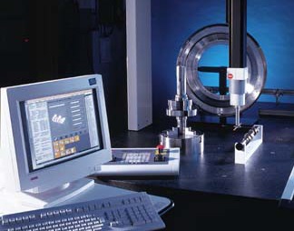
and CAD/CAM/CAE systems. During the past five years, CMM software has improved in function and data analysis capability, making software upgrades an inexpensive way to achieve maximum measurement and inspection performance with coordinate measuring machines. Upgrades are cost-effective when compared with personnel or new CMM expenses. Today’s measurement software can link with other computer systems, providing the economic advantage of a common measuring system throughout production facilities. In addition, new software is more powerful and can perform functions that older versions weren’t designed to handle. The following overview and profiles of two companies’ successful upgrades amply illustrate the benefits of advanced measurement software for CMMs. Improvements have expanded and simplified the user interface and developed links between measurement software and CAD/CAM/CAE systems. For the past decade, measurement-and-inspection software has employed an icon-based user interface to eliminate keyboard commands and help operators navigate through fundamental measurement processes such as alignment, probe qualification and selected routines. Newer metrology software uses icons and other graphic devices in deeper program levels so that operators can literally point and click their way through complex measurement routines. The number of preprogrammed inspection routines also has increased significantly. Today, measurement-and-inspection software is available with modules that allow non-specialists to easily inspect complex shapes and forms such as turbine blades, compressor scrolls and screws, rotors, gears, cams, pistons and sheet metal assemblies. These application-specific modules are accessed simply by selecting the appropriate icon and following on-screen instructions. Using advanced algorithms, software engineers have overcome many data associativity problems to the point where data transfer between systems is virtually seamless. Measurement software functions now routinely incorporate translators that allow the software to communicate with CAD/CAM/CAE systems. Improving inspection throughput and uptime L&S Machine Co. Inc., an aerospace machine shop in Wichita, Kansas, experienced marked improvement in inspection throughput and overall productivity with advanced software. Rather than buy more measurement equipment and double its inspection staff, the company installed PC-DMIS for Windows, a graphics-coupled software from Brown & Sharpe, on its three CMMs. The company now machines 500 different aerospace part numbers a year, compared with about 250 part numbers just two years ago. The parts typically are complex three-, four- and five-axis components with true position tolerances down to 0.001 inch. Before installing the software, in- process inspection at L&S Machine was complicated. Operators had to memorize numerous codes to access the various programming and measurement features. Even performing rough, in-process checks was time-consuming because every set of points measured required its own program. Writing a conventional CMM part program used to take the company about 40 to 80 hours. That is down now to about 16 to 40 hours, depending on the part’s complexity. A feature in the new software allows operators to use the original design data’s accuracy to create off-line inspection programs with graphical part models and probe path simulations. The software downloads 3-D part models from any computer-aided design system and creates a graphical representation of the part. The CMM operator then simply clicks on any surface or feature of the model to create a direct computer control inspection program. Inspection results can be uploaded directly to the CAD system by IGES and DMIS links. While conventional programming typically is performed as a teach-and-learn operation at the CMM, an off-line version of PC-DMIS allows operators to program on a personal computer. Part programming at L&S Machine now begins before the first piece has been manufactured, and CMMs are available more often for measuring parts. The new software also has helped L&S Machine improve uptime for production equipment from 60 to 75 percent several years ago to an average of 95 percent today, primarily by reducing hard gaging on the shop floor. Formerly, operators would set the parts up on hard gages for first-piece inspection. Now they are responsible only for three simple hand measurementswall thickness, radius and hole location. Parts are sent directly to the CMM for first-piece inspection while the machine operator runs a proven part already set up on the machine tool. A typical first-piece inspection on the CMM will check hundreds of features in about half an hour; checking 50 features in the shop with a hard gage used to take about four hours. Design advantages with reverse engineering In addition to reducing part programming time, the CAD interface capability of new measurement and inspection software also allows reverse engineering functions. This is particularly helpful in establishing accurate CAD models when mathematical data is unavailable. Operators use a screen drawing of the part to select dimensions that require measuring, and measurement parameters are entered quickly by filling out simple menus. The key to this advanced capability is scanning software that not only controls the motion of the CMM but effectively captures and evaluates massive volumes of surface point data. Once rare and extremely expensive, this software is now widely available at affordable prices. Advanced scanning software, combined with a CAD system interface, has been used successfully in automotive manufacturing operations to help reduce overall manufacturing time. Designing and producing car bodies currently requires 3-D surface models of the parts. Expensive iterations on models are needed to refine part surfaces and transform stylists’ concepts into efficiently producible products. Consequently, closer interactions between stylists and model makers can help save weeks of development time. A large, gantry-type CMM, equipped with advanced software and accessories, is an excellent tool to support automotive design activities and production engineering operations, as well as improve die and mold design and manufacturing for large contoured parts such as car bodies and subassemblies. Gantry CMMs can be equipped with continuous path-scanning software that supports tactile and laser scanning probes for fast and accurate model digitizing and produces part programs to control numerical control milling machines. The surface data points generated by the system can be directly imported into a CAD workstation to create a mathematical representation of the part geometry. The surface data points may also be post-processed by the CMM computer to produce a cutter path for all machining passes, from rough cutting to finishing, for efficient model copying. Easy-to-use reverse engineering functions also simplify the process of modifying the style model after engineering or manufacturing changes on the final part. These functions allow CAD/CAM data to be generated directly from the part scanning files. In a typical reverse engineering application, a part model may have been initially machined from a CAD file and later modified by hand to meet functional or manufacturing requirements. By scanning the model’s modified areas, the operator can create useful data to embody these changes in the original part database. Direct model copying functions for die and mold making are supported by advanced software features such as cutter radius compensation and automatic model alignment. These allow process optimization, and save time and money. A powerful light milling software function transforms the gantry CMM into a numerical control milling machine to build complex surfaces on soft materials such as clay, polystyrene, epoxy and aluminum. Reducing development time The Advanced Styling Department of PSA-Peugeot Citroën has reduced the art-to-part cycle for car bodies by adopting a digitizing/measuring/milling system for styling applications. Their objective was to use the latest CMM and software technology to cut months off product development time while improving the quality of complex, multisurface models. The system includes a large CMM; an analog scanning probe to continually digitize unknown 3-D free-form shapes; a noncontact laser probe for accurately scanning soft materials; an electronic touch-trigger probe that performs precise tactile measurement of geometric dimensions as well as stitch scanning on predefined shapes; and a point-to-point laser probe for noncontact measurement of soft pieces. All probes are held on a two-axis indexable head that properly orients them in space for accurate surface measurements. The machining functions are supported by a variable-speed milling head. The gantry is equipped with Tutor for Windows measurement software and continuous path scanning and milling software options. PSA-Peugeot Citroën operates in an integrated process environment with computer-assisted design and engineering. A car’s style model is first developed in a CAD/CAM/CAE environment, where a part geometry database is created. The computer-controlled gantry CMM then mills on a clay profile grid the style model from the CAD data file. The physical model is hand-worked to complete and refine one side of the vehicle’s shape. The CMM then scans the modified model and reverse-engineers its surfaces from the point data. The body’s complete clay model is obtained by milling its symmetrical second half, using the system’s powerful mirroring functions. Critical body details, such as window drops and door joints, are added subsequently to the clay model by milling their CAD geometries. This first physical model undergoes a series of wind-tunnel checks and is reshaped and streamlined to optimize its aerodynamic behavior. The final clay model’s contours are then completely scanned and downloaded to the CAD/CAM system to fully document its shape, and a tape is created to cut copies of the body and its details. These copies are verified by checking their critical dimensions in point-to-point mode on the gantry, using both tactile and noncontact probing techniques. The final model’s forms also are sent to subcontractors and to the company’s engineering departments for die production. The above examples from L&S Machine and PSA-Peugeot Citroën illustrate two approaches to software upgrades. The initial goal at L&S Machine was to improve inspection throughput without increasing inspection costs. The goal at PSA-Peugeot Citroën was to reduce product development time by facilitating communications between styling and modeling operations. In both cases, the companies achieved their objectives and discovered other benefits as well, simply by improving the efficiency of their operations with new measurement software. Intuitive Software Simplifies User Interface  RefleX software by Brown & Sharpe exemplifies a new approach to operator interface. Installed on the company’s Gage 2000 R series measurement station, the software uses not only icons but membrane switches in the form of touch buttons on a machine-mounted controller, similar to the controllers used on machine tools. RefleX software by Brown & Sharpe exemplifies a new approach to operator interface. Installed on the company’s Gage 2000 R series measurement station, the software uses not only icons but membrane switches in the form of touch buttons on a machine-mounted controller, similar to the controllers used on machine tools.
The software is designed to enable operators to choose the measuring instrument they want to usecaliper, dial indicator, height gage or a full-featured CMMsimply by following instructions on the monitor and pushing buttons. The software identifies the part feature as it’s being measured and draws it on the controller’s VGA monitor. During the measuring routine, work piece dimensions are compared to nominals, and out-of-tolerance conditions are indicated on the controller’s screen. RefleX simplifies normally complex operator tasks such as part setup. The operator touches the probe to a part surface, an axis and the origin; the software does the rest. A wealth of dimensional data about the part feature being measured, such as true position, squareness, parallelism and feature relationship, can be easily accessed by pushing the icons on the touch screen. Measurement data can be automatically transferred from Gage 2000 R via an RS-232 serial port to a shop-floor data collector for archiving and process control analysis. Data can also be sent to an optional printer via a parallel port for a hard copy of inspection results. Gage 2000 R can be used as a full-featured CMM with a manual scanning option. The manual scanning mode allows operators to quickly collect a large number of data points by moving a hard probe along a work piece surface, maintaining contact with the work piece throughout the operation. A scanning “speedometer” graphically indicates the quality of the measurement data being collected based on probe speed. An optional utility converts probe center points to standard CAD formats such as DXF and IGES for reverse engineering applications. About the author For the past 22 years, David H. Genest has been involved in product engineering, development and marketing at Brown & Sharpe Manufacturing Co. in North Kingstown, Rhode Island. He is currently director of marketing and corporate communications for the company. Genest’s background in metrology system design and development includes the introduction of Brown & Sharpe’s process control robot and other systems for shop floor measuring and inspection applications. Genest may be contacted by e-mail at dgenest@qualitydigest.com. |