|
Perhaps the most important tool in process control, an optical gaging instrument provides managers with tremendous versatility. These noncontact gaging instruments enable manufacturers to inspect a wide variety of parts without using complex fixtures. Characteristics such as feature size, shape, location or surface finish can easily and rapidly be determined with these instruments.
In the beginning
The first optical inspection instruments were developed to enhance the human eye's ability to see certain aspects of an object. These simple lenses magnified an image and allowed users to discern features they couldn't otherwise see. Although early optical gages allowed inspectors to view and compare objects, they didn't allow objects or features to be accurately meas-ured. Accurate measurement requires that the object under observation be compared to a standard of known size.
This principle was first applied in shadow graphs. These instruments used a lamp to project a two-dimensional image of an object onto a flat surface. The shadow could then be measured with a known standard, such as a ruler, to determine its size. By placing a magnification lens in the path of the projected image, an inspector could enhance or magnify it for greater clarity of certain features. Shadow graphs often projected the image onto a grid of known size so that the operator could determine the object's size by counting the number of squares the object's shadow occupied and then dividing that number by the magnification of the objective lens.
Overlay charts also were developed that allowed an operator to compare the shadow projected with a drawing of the feature under inspection. To determine a feature size or shape quickly, this overlay often included two drawn images. One indicated the minimum allowable size of the part's tolerance, while the other specified the feature's maximum allowable size. The operator determined whether the part was good or bad simply by inspecting the screen to ensure the shadow fell between these two lines. Although this comparison method allowed an inspector to determine if a part was in or out of tolerance, it wasn't readily adaptable for inspecting a wide variety of parts and shapes.
As optical gaging evolved, manual micrometer heads were fitted to stages or tables that slid along the machine's horizontal and vertical axes. This increased versatility by allowing inspectors to directly examine a feature's size or location without using an overlay chart or grid. They could line up one edge of the shadow being projected on a screen cross line and then move the stage micrometer to the shadow's other end. The distance that the stage traveled equaled the part's dimension. With this principle applied to both X and Y axes, comparators could measure any two-dimensional feature projected on the screen.
The major turning point in optical gaging occurred when instrument manufacturers replaced manual micrometer heads with electronic encoders and digital readouts. Electronic encoders mounted to the stage send a signal to a digital readout, which decodes the signal and displays the distance and direction the stage traveled. The first digital readouts simply displayed the stage's X and Y locations. However, once microprocessor technology was included in digital readout designs, geometric principles could be used to calculate features such as angles, radii and relative position. This further enhanced optical instruments' capabilities.
At about this time, video technology was developed that replaced the standard projection system with a lens and camera system. The part being inspected is digitized, manipulated and displayed on a TV-style monitor. Recent developments and improvements in this technology include the ability to measure in all three dimensions because the "Z" or focus axis can now be controlled automatically.
Types of optical gages
Optical inspection instruments fall into four basic categories: optical comparators, video systems, microscopes and laser systems.
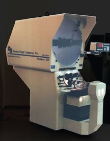
Optical comparators use traditional optics to magnify and project an object's image onto a glass screen. This type of optical inspection instrument is by far the most widely used and is also the least expensive method of optical noncontact inspection. It also offers the greatest versatility because lightweight parts as well as ones weighing hundreds of pounds can be inspected on many available instruments. The optical edge finder, developed later, eliminates the operator's subjectivity from the measurement and allows the system to be fully automated.
Optical comparators are available in numerous styles and configurations from domestic as well as international manufacturers. Typical options include projection screen sizes from 10" to 80", horizontal or vertical light path configurations, profile and surface illumination systems, various stage travel options, magnifications from 5X to 200X and digital readout options such as a basic two-axis display and automatic computer numeric controlled systems. Accuracy and repeatability of instruments currently available can vary depending upon the feature being inspected but usually fall within ±0.00010" under certain conditions.
Video systems using a magnification lens and camera are relatively new to the mainstream inspection instrument market. Although these systems typically cost more than optical comparators, they offer less versatility with regard to the size and weight of parts that can be inspected. However, these shortfalls often are more than offset by the advantages offered. Vision systems, generally small and compact, work best with relatively lightweight and/or flat parts. Camera and computer advancements offer magnifications in the 1X to 1,300X range; some even offer full, three-axis measurements under CNC control.
Video-edge detection also is available, which eliminates operator subjectivity from the measurement process. The image digitization process used by video systems also allows for computer manipulation and storage of the displayed image. When connected to a printer and driver, a video inspection system can print out a pictorial view of the inspected part for documentation purposes. Due to specialized staging, computer manipulation of lighting, image processing and extremely high magnifications available, some vision systems' accuracy and repeatability can fall within ±0.00005" under certain conditions.
Inspection microscopes use traditional optics to magnify a desired detail. Many inspection microscopes today are coupled with a video system and offer manual optical inspection as well as automated video inspection. These microscopes generally work best when inspecting lightweight and/or flat parts.
Laser inspection instruments, the latest development in optical inspection, offer the greatest accuracy of any optical inspection instrument. Accuracy and repeatability within ±0.0000010" under certain conditions can be expected. This type of instrument utilizes a reflected laser beam to accurately determine distances by using time delay calculations. Extremely specialized, laser inspection instruments require fixturing to locate the laser device as well as substantial setup time to align the instrument. This measurement method is best suited for specialized production inspection or calibration applications.
Technologies in development
An operator's subjectivity can drastically affect the measurement being performed--a traditional and major drawback with optical inspection instruments. Vast differences between measurements are commonplace because the instrument operator determines where the feature being inspected begins and ends.
However, the recent advent of the optical edge finder, available on both optical comparators and video systems, has eliminated this problem. Edge-finding systems also allow a control computer attached to the measurement system to detect a feature automatically. This capability enables instrument manufacturers to fully automate these instruments.
Full CNC, motorized inspection instruments that entirely eliminate operator subjectivity are now available. Major cost reductions in electronics and system standardization has made these systems affordable to just about every manufacturer. Optional edge-finding systems that cost thousands of dollars only a few years ago have now become standard equipment on many models.
Many other changes have occurred within the inspection industry during the last decade. As manufacturing tolerances decrease, accuracy and resolution of the instruments used to control manufacturing must increase. The typical measurement resolution of an optical inspection instrument has improved tremendously within the last nine years, from 0.0005" to 0.00005" today. Miniaturizing electronics has made video inspection technology increasingly cost- and feature-competitive to optical comparators. Within the last dec-ade, the cost of video system technology has decreased by a factor of 12, while the features and benefits of these systems have actually increased.
Integrating desktop PCs as the primary processing platform with inspection instruments has increased these systems' capabilities and features, and allowed inspectors to document their products. These systems' processing speeds have increased by a factor of 15 during the past six years alone. Future cost reductions and integrating computers into these optical inspection instruments will increase their speed and versatility.
Traditional optical inspection instruments now are combined with contact measurement devices such as touch probes. These hybrid instruments can take advantage of both contact and noncontact measurement solutions to rapidly inspect virtually any desired feature.
The quality department's role in manufacturing
As manufacturers strive for Six Sigma manufacturing proc-esses and zero defects, the quality department's role has changed significantly. Quality departments now are actively involved in the manufacturing process, from engineering to product packing and shipment. Optical noncontact and hybrid optical/contact inspection systems provide the tools necessary for quality managers to accomplish this. With computerized optical systems, statistical process control software packages can be integrated directly on the inspection instrument. These computerized instruments are network-capable, making documentation control and maintenance automatic and paperless. These instruments can and will be connected via a company's network to the engineering department's computer-aided design system. The quality department can then download and import product part prints for automated programming of inspection routines.
Networked optical systems also will allow the quality department to export and upload actual inspection results in CAD format for the engineering department to review. In addition, traditional contact production gages, such as snap gages or bore gages, can be integrated via SPC connections into the inspection package to provide a complete quality solution.
A bright future
As optical inspection technology matures, becomes more automated and combines with other inspection technologies, inspection instruments will become completely integrated with the manufacturing process. Complex inspection systems will inspect a manufacturing process online while the parts are manufactured. Optical inspection instruments offer a noncontact measurement technique that will allow part inspection while the part is actually moving and being machined on the machine tool. Automated communication between the inspection instrument and the machine tool will close the loop and provide the machine tool with the necessary offsets and adjustments to meet the goal of any manufacturing process, which is to manufacture a virtually perfect part, every time.
About the author
Peter Klepp is assistant vice president of Dorsey Gage Co., located in Poughkeepsie, New York. Dorsey Gage is a leading manufacturer of quality inspection instruments. For more information, contact the company by fax at (914) 454-3140 or e-mail pklepp@qualitydigest.com. |