| by Jeff Walker
In a perfect world, every CMM would be built entirely
of “unobtanium,” a well-known fictional aerospace
material that possesses exactly the combination of properties
needed to achieve some otherwise unachievable goal. The
variety used in the perfect CMM has a zero coefficient
of thermal expansion, infinite stiffness and no mass. Housed
in an absolute vacuum at zero K and operated by tractor
beams, which induce neither heat nor stress into the structure,
it would be the ideal CMM. Unfortunately, we don’t
live in a perfect world.
Our CMMs are subject to myriad error-inducing factors,
including dynamic thermal and mechanical stresses, inconsistent
and nonlinear material responses, inappropriate human inputs,
and--perhaps the greatest error-inducer of all--economics.
CMM builders counter these error-inducers with a toolbox
that includes good design, carefully selected materials
and sophisticated software-based compensation systems--but
it’s an ongoing, uphill battle.
Because we live in the computer age, CMM designs in the
past few years have emphasized software compensation tools.
Great strides have been made and continue to be
made in this arena. But as these tools get better and better,
the limits of their ability to improve CMM performance also
become clearer.
It’s now possible, for example, to compensate for
thermal errors in the entire structure of a CMM, all the
way from the baseplate to the very tip of the probe. Moreover,
today’s best software can place the virtual origin
point for thermal expansion calculations anywhere on the
machine--not just at the mechanical datum point--to minimize
distance-related translation errors. Compensation for mechanical
errors is equally sophisticated.
Compensation algorithms are very good and getting better,
but they’re ultimately discrete digital systems applied
to a dynamic analog reality. The fit is not, cannot, and
never will be perfect.
To make matters even more difficult, random influences
like thermistor tolerances and thermal response variations
within individual samples of the same material are also
present in the real world. In practice, these factors produce
an inescapable residual error that can be as high as 10
percent.
Considering that the coefficient of thermal expansion
for aluminum is nominally 23 ppm per degree Celsius, a
1° C change in temperature can produce an uncontrolled
and uncontrollable potential compensation error of 2.3 µm
in just a 1 m length. More costly components and more frequent,
time-consuming calibration routines can reduce the residual
error, but it can never be totally eliminated because it’s
inherent in the compensation process itself.
Today, we’re beginning to recognize the ultimate
limits of software compensation, and tomorrow we’ll
be bumping hard against them. In the future, the gains
from this technology will be progressively smaller while
the cost of each increment in terms of hardware expense
and machine utilization will be significantly higher.
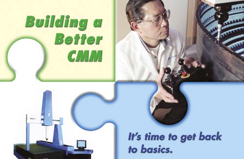
If software compensation appears to be reaching its practical
limits, what else can be done to improve the performance
of today’s and tomorrow’s CMMs? The answer
is most likely a return to the basics of engineering a
stiffer, more stable and smoother operating platform that
will minimize the amount of compensation required in the
first place.
That process will include the use of new materials, better
bearings and more sophisticated designs for all of the
components and subsystems of a CMM. This will be complicated
by the need to achieve higher performance at a lower relative
cost while providing more usable uptime and greater application
flexibility to the CMM consumer. It’s a tall order.
When it appeared that software compensation would be
the ultimate solution to the problem of thermal growth
in CMM components, aluminum became a favorite engineering
material with many machine builders. Relatively stiff,
light, easily machined and inexpensive, aluminum’s
only major flaw is its high thermal response rate. This
is a negative that everyone believed software compensation
would easily overcome.
Today we know better. Most high-end CMMs, and a growing
number of mid-range and even low-end machines, now use
some form of ceramic or composite for the critical bridge
beam structure. The reason is that ceramics are extremely
stiff, relatively light and thermally stable. One of the
better ceramic materials, polycrystalline aluminum oxide,
is a full 330 percent stiffer than aluminum, yet it’s
only 32 percent heavier and has less than a quarter of
aluminum’s coefficient of thermal expansion.
Assuming the same 10 percent residual error in the software
compensation system discussed earlier, a ceramic beam would
have a compensation error of only 0.6 µm in the same
1 m length, whereas aluminum has an error of 2.3 µm.
It’s still not perfect but much smaller and therefore
much less detrimental to the overall accuracy of the measurement
being taken.
But thermal growth isn’t the only stability issue
in CMM design. Dimensional changes related to both static
and dynamic mechanical stresses must also be considered
and compensated for. Unless they’re somehow relieved,
every material has some level of stress locked into its
crystalline and/or mechanical structure during its creation
or fabrication.
In machined or fabricated metallic components, these
stresses can be significant, even after artificial stress-relief
processing. In the case of natural materials like granite,
such stresses are negligible because of millions of years
of natural stress relief. That is one
of the reasons granite is the universally preferred material
for CMM bases. Modern polycrystalline ceramics fall somewhere
in between but are much closer to granite in natural stability
than they are to fabricated metallic components.
Stability is greatly influenced by good mechanical design,
particularly of the interfaces between components. So-called “kinematic” design
strategies strive to minimize--and ultimately eliminate--the
introduction of any stress into a structure at its various
mechanical interfaces. Although the subject of
kinematic design is too broad and detailed for this discussion,
it’s widely used in fixture design where the classic
3-2-1 location system provides an excellent example of
its application.
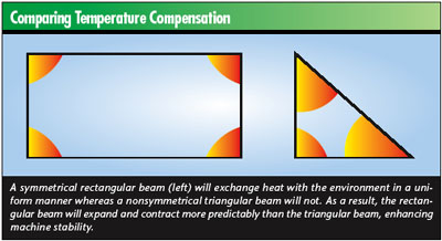
Achieving optimum stability in a structure such as a
CMM requires a detailed analysis of every component in
the structure. Even the shape of a beam can make a significant
difference in its thermal and dimensional performance.
For example, corners tend to be thermal stress points
because they heat and cool more quickly than flat surfaces.
As a result, rectangular structures tend to be more stable
than triangular structures because the corner-induced stresses
are symmetrical.
However, triangular structures are both lighter and less
expensive than rectangular structures of the same capacity
because they contain less material. They’re also
easier to fit with preloaded air bearings, as illustrated
on page 41.
A cost-driven design will choose triangular beams, whereas
performance-driven design will choose the more costly rectangular
beams. Over the long run, however, the more expensive design
will prove to be the more cost-effective because it’s
substantially more stable, and that means it requires fewer
recalibrations and delivers more usable uptime. In the
end, stability translates directly into reduced measurement
costs for the end-user.
Stiffness is the second major goal in CMM design, and
stiffness without mass is the essential characteristic
of CMM-style unobtanium. Materials with high stiffness-to-weight
ratios tend to minimize many of the mechanical errors inherent
in CMM design. Stiff, light real-world materials reduce
the mass of moving elements, permitting smaller drives,
less heat, shorter measuring cycles and lower costs.
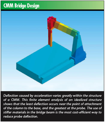
The greater stiffness of ceramic beams shows up in analyses
of bridge behavior under acceleration. When accelerated,
the bridge beam is subjected to a directional deformation
force directly proportional to the acceleration. For an
aluminum beam, the resulting directional deformation is
nearly twice that of an equivalent ceramic beam, despite
the fact that the ceramic component is 32 percent heavier.
In practical terms, this means the ceramic beam can be
accelerated nearly twice as fast as the aluminum beam while
maintaining deformation within a comparable range. Greater
acceleration translates directly into shorter traverse
time and reduced cycle time for any given movement and
ultimately into a lower total cost for any given inspection
task.
Another material with greater stiffness than aluminum--200
percent, to be exact--is steel, which is used increasingly
in structural components such as support legs on advanced
CMMs. Because of its high
strength, steel--like ceramic materials--offers an opportunity
to design structures with enhanced performance and only
a small weight penalty compared to aluminum. And, like
ceramics, steel’s greater stiffness permits higher
acceleration and reduced cycle times and inspection costs.
Most CMMs today use air bearings to support moving components,
but all air bearings do not deliver the same level of performance.
The key influence on air bearing stiffness is the gap required
to support a given load--the smaller the gap, the stiffer
the bearing, all else being equal.
Conventional air bearings, the type used on most CMMs,
generally have several orifices placed in a pattern across
the otherwise smooth face of the bearing “pad.” These
orifices distribute pressurized air to lift the pad away
from the surface to create the bearing gap and support
the load.
There is another design, however. It has been found that
creating an annular groove on the pad face and connecting
it to one or more orifices using straight grooves produces
a more efficient bearing. The performance difference is
dramatic.
For a given load, surface area and air volume, the plain
bearing will have 3.5 times the gap of the grooved design.
Viewed from the stiffness perspective, with all else being
equal, the grooved bearing delivers 140,000 N/mm compared
to the plain-pad design’s 40,000 N/mm.
In the context of a CMM, this greater stiffness translates
directly into enhanced accuracy but also means the moving
elements can accommodate greater accelerations. As is the
case with stiffer materials, greater acceleration made
possible by stiffer bearings also means shorter cycles
and reduced measurement costs.
Although software-based compensation systems are rapidly
nearing the point of diminishing returns, the same cannot
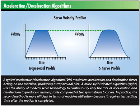
be said for software-based motion control efforts. Today,
most CMMs use a simple acceleration/deceleration algorithm
that produces a trapezoidal plot. The strategy is to accelerate
to maximum velocity as quickly as possible, maintain that
velocity as long as possible, and then decelerate to zero
as quickly as possible, as illustrated below.
At first glance, this strategy might appear to deliver
optimum cycle times. After all, going as fast as possible
should be the key to getting from point A to point B in
the minimum amount of time; in a large, robust structure,
it may well be.
But CMMs are not large, beefy structures. For a CMM,
this strategy produces a substantial wait at the end of
the motion while the machine “settles down” and
dissipates the stresses and vibration generated by the
acceleration/deceleration process.
A better strategy is to control the motion to produce
a pair of gentle “S curves” during acceleration
and deceleration. In practice, this approach may add a
fraction of a second to the traverse time from point A
to point B, but this will be more than compensated for
by the reduction of waiting time once point B is reached.
In an intermittently used laboratory machine, the difference
may be negligible. But, in a production-monitoring application,
which fully utilizes the CMM’s capabilities, the
difference in cost-per-measurement can be substantial enough
to pay for the more sophisticated capabilities in a short
time.
No discussion of modern CMM design is complete without
some mention of scanning--unquestionably the technology
of the future. Because scanning is done “on the fly,” taking
measurements with all elements of the machine in motion,
it will quickly surpass the capability of software-based
compensation systems--unless the machine is designed from
the ground up to minimize the need for such compensation
systems. It’s already happening.
It’s time for the industry to get back to basics
and engineer CMMs that are optimally stable, stiff and
smooth, independent of the compensation system. The materials
exist, and none of them are “unobtanium.” The
technology exists. It’s time to shift the industry’s
primary focus away from compensation and back to sound
design.
Jeff Walker is manager of marketing and new products
at LK Metrology Systems Inc. in Brighton, Michigan.
|
 Stiffer machines