|
The automotive industry has
long been driven by demands for better fuel economy and
lower exhaust emissions. In Europe these forces have led
to a resurgence of the once-lowly diesel engine. Early diesels
were often perceived as dirty and noisy but cheap and easy
to operate and manufacture. In contrast, the latest generation
of passenger car diesels is quiet, clean, efficient and
powerful. These improvements result largely from the development
of high-pressure fuel injectors that provide thorough mixing
of fuel and air as well as precise control of the injection
profile.
"If you can't measure it, you can't make it."
Never was this adage more true than during the development
of these new injectors. With operating pressures approaching
30,000 psi, they require sealing and bearing surfaces with
form tolerances as tight as 1 micron. To further complicate
matters, the critical surfaces sit at the blind end of a
long, narrow bore, making them difficult to access. Conventional
measurement technologies offered neither the necessary accuracy
nor the speed to control such a high-volume production process.
To meet this need, Corning Tropel Inc. developed a laser
interferometric metrology system that combines submicron
accuracy with measurement and setup times on the order of
one minute per measurement. Although developed specifically
for fuel injectors, the technique will likely apply to other
high-value manufacturing processes that incorporate deeply
recessed, rotationally symmetric surfaces.
 Diesel
engines possess a fundamental fuel efficiency advantage
over spark-ignition gasoline engines. In addition, diesel
fuel is both less expensive to produce and, because it's
less volatile, safer to use than gasoline. These advantages
have long secured the diesel engine's position in industrial
applications, in which purely economic considerations outweigh
those of aesthetics. But who hasn't changed lanes to avoid
following a smelly, smoky diesel on a long, slow climb,
or cast uncharitable thoughts toward the smug driver who
saves his fuel dollars at the cost of our fresh air? Diesel
engines possess a fundamental fuel efficiency advantage
over spark-ignition gasoline engines. In addition, diesel
fuel is both less expensive to produce and, because it's
less volatile, safer to use than gasoline. These advantages
have long secured the diesel engine's position in industrial
applications, in which purely economic considerations outweigh
those of aesthetics. But who hasn't changed lanes to avoid
following a smelly, smoky diesel on a long, slow climb,
or cast uncharitable thoughts toward the smug driver who
saves his fuel dollars at the cost of our fresh air?
All of this is about to change. The diesel has been reborn,
and from the soot have risen smooth, powerful, clean and
quiet engines that maintain fuel economy. This renaissance
began during the early 1990s in Europe, where high fuel
prices underscore the benefit of the diesel's economy and
strict regulations limit exhaust emissions. Luxury car manufacturers
Alfa Romeo and DaimlerChrysler were the first to introduce
the new diesel technology, and they were quickly followed
by others. Between 1996 and 2001, the percentage of newly
registered European cars with diesel engines had more than
doubled. Volkswagen currently holds the fuel economy record
of 100 km on less than a liter of fuel. At the performance
end of the spectrum, Volkswagen will soon introduce a five-liter,
10-cylinder engine that produces more than 300 horsepower,
and a diesel BMW recently won the 24-hour endurance race
at Nürburgring race track in Nurburg, Germany. In terms
of cleanliness, the emission of noxious engine substances
has dramatically dropped during the last 10 years. Particulate
emissions are down 80 percent, nitrous oxide by 90 percent
and carbon monoxide by 97 percent.
High-pressure fuel injection systems lay at the heart
of the diesel renaissance, led by pioneering manufacturer
Robert Bosch GmbH. High-injection pressure promotes finer
fuel atomization and better mixing with air to ensure complete
combustion. When combined with electronic actuation, the
high pressure also permits precise control of the injection
timing and volume. Bosch recently announced the delivery
of its 10 millionth high-pressure injector and delivered
more than 4 million during 2002. This compares to only 200,000
delivered as recently as 1999.
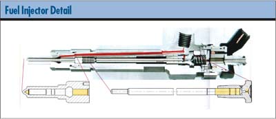
A fuel injector is fundamentally a highly sophisticated
needle valve (See below). Injector ports at the bottom of
the valve direct the fuel into the combustion chamber in
a precisely controlled pattern, and a solenoid or piezoelectric
actuator opens and closes the valve. Precision mechanical
surfaces include the guide bearings, cylindrical surfaces
on the shaft of the needle and body that control the needle's
alignment; and the valve surfaces, mating conical surfaces
that control the flow of fuel. Thirty-thousand psi operating
pressures require form tolerances on these surfaces as tight
as one micrometer. The critical valve seat is typically
located at the bottom of a blind hole a few millimeters
in diameter and tens of millimeters deep. Created by grinding,
these surfaces can be relatively rough.
In any high-volume manufacturing process, control is essential
to high yield and maximum profitability. As operating pressures
and manufacturing volume climbed, engineers soon realized
that they had no adequate means of measuring their manufactured
surfaces at an adequate speed. Contact methods lost much
of their precision in the inaccessible blind hole and weren't
fast enough to provide a high-density surface map in a reasonable
period of time. Optical methods also ran into problems with
accessibility and the roughness of the measured surfaces.
Developing a viable measurement technique became essential
to continuing progress in fuel injector manufacturing.
 Corning
Tropel's ThetaForm is a miniaturized, dual-wavelength interferometer
configured to measure difficult-to-access, rotationally
symmetric surfaces. Corning
Tropel's ThetaForm is a miniaturized, dual-wavelength interferometer
configured to measure difficult-to-access, rotationally
symmetric surfaces.
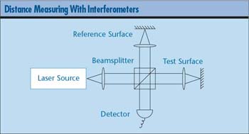
In distance-measuring applications, interferometers work
by comparing the distance traveled by one beam of light,
the test beam--which reflects back to the interferometer
from the measured surface--with the distance traveled by
another beam, the reference beam--which reflects back from
a reference surface fixed at some arbitrary distance, as
illustrated to the left. The interferometer makes the comparison
by looking at the way in which the two beams interfere when
recombined. If the crests and troughs of the test and reference
beams coincide when they return to the interferometer, they're
said to interfere constructively. The difference between
the distances traveled by the test and reference beams must
be an even multiple of half the light's wavelength. However,
if the crests of one beam coincide with the troughs of the
other (i.e., 180 degrees out of phase), they interfere destructively,
and the distance difference must be one-quarter of the wavelength
greater or less than an even multiple of the half-wavelength.
Adjacent points spread over a surface will compose a pattern
of dark and light bands, with the dark bands corresponding
to destructive interference and the light bands corresponding
to constructive interference. The overall pattern represents
the deviation of the shape of the test surface from the
shape of the reference surface.
With the ThetaForm system, the interference map comprises
sequential measurements acquired point-by-point as the test
surface rotates on its axis in close proximity to the interferometer
probe. The probe is mounted to a programmable stage that
can move left, right, up and down, thus allowing the probe
to follow the surface in a spiral pattern over any rotationally
symmetric form. The test beam passes through the probe,
reflects from the surface and returns through the probe
to the interferometer. The interferometer's reference arm
travels with the probe but not through it; therefore the
interference map represents the deviations of the test surface
from an ideal, virtual surface symmetric about the rotational
axis of the measured part.
The wavelength of the light provided by the laser sources
used in interferometry is precisely known and extremely
stable; thus, the measurements offer reliable precision
and accuracy. Using specialized analytical techniques, it's
possible to resolve point-to-point distance changes of one-hundredth
of the wavelength or better. The ThetaForm uses two lasers
with wavelengths of 1,310 and 1,550 nm that offer point-to-point
resolution of a few nanometers.
Although they're highly precise, interferometers have
limited dynamic range. Because each light wave is exactly
like every other wave, an interferometer is like a ruler
without numbers (i.e., it can accurately measure fractions
of an inch, but it has a hard time distinguishing one inch
from another). As a rule of thumb, interferometric measurements
require a surface roughness much less than the wavelength
of the light. The ground surfaces found in fuel injectors
can easily exceed this criterion. However, the ThetaForm's
dual wavelength interferometer offers a solution. By combining
the interferometric patterns at the two different fundamental
wavelengths, it generates a composite pattern with a synthetic
wavelength of 8.46 mm. Both interferometers are independently
capable of measuring smooth parts. Together they can measure
ground parts with surface roughness (Rz) up to 2 mm.
One of the most difficult surfaces to access on a fuel
injector is the valve seat, which is located at the bottom
of a deep, narrow hole. The ThetaForm's probe design allows
the test arms of both interferometers to be delivered to
the bottom of a 3.5 mm diameter by 45 mm deep blind hole,
as illustrated to the left. At the end of the probe, miniature
optics split the test arms into two different beams. The
beams each contain both wavelengths but leave the probe
at different angles, permitting measurements of two different
surface types with the same probe. Because neither the part
nor the probe is disturbed between measurements, the system
can make relational measurements such as runout, perpendicularity
and coaxiality among different regions of the part. For
example, the fuel injector requires precise alignment of
the guide bearing and the valve surfaces.
The interferometers and probe ride on an X-Z stage system
that allows the probe to follow the part surface. Although
it's a high-precision, crossed-roller bearing stage, its
motion isn't perfect. A separate, three-axis displacement
measuring interferometer constantly monitors the straightness,
yaw and displacement errors of the stage motion. Stage position
data is recorded for each measured point, permitting error
correction during subsequent processing.
The part is mounted to a precision air-bearing spindle
by a hydraulic expansion chuck. Software analysis after
the measurement removes any residual tilt or decenter--typically
less than a few microns.
The stages, interferometers and spindle are mounted on
a granite base, which is suspended by a pneumatic isolation
system. They're enclosed in an actively controlled environmental
chamber that maintains the entire measurement area at a
constant temperature within +_ 0.25° C.
At 600 rpm, data acquisition time for typical measurements
is short. Even allowing time for sample mounting, probe
positioning and data analysis, total measurement throughput
equals a minute or two per measurement. Moreover, the high
sampling density provides thorough coverage of the full
surface and minimizes the probability of significant sampling
error.
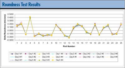
The repeatability of these measurements has proven to
be quite good. We can typically achieve a standard deviation
of 10 to 30 nm, depending on the parameter being measured.
For example, a roundness test of the inside cone for 25
different parts was measured 20 times during a period of
five days, as illustrated below. For this set of data, the
average standard deviation was 11 nm.
The measurements' accuracy is verified by NIST/PTB-certified
artifacts. Corning Tropel has manufactured artifacts for
each of the measured parameters: roundness, straightness,
parallelism, angle, diameter and runout. Gage studies comparing
the measured values to the certified values achieved an
accuracy of 40 nm or better for each of these parameters.
High-pressure fuel injectors have permitted dramatic improvements
in automotive diesel engines. The new generation of engines
will ultimately affect the lives of millions, not only by
improving the quality of the driving experience, but also
by reducing the negative environmental effects of driving
we all share. The new injectors' performance, however, is
heavily dependent on maintaining extremely tight manufacturing
tolerances that, until now, have been difficult or impossible
to measure. Although the ThetaForm was developed to satisfy
the specific requirements of injector manufacturers, it
will certainly apply to other precision manufacturing operations.
Thomas J. Dunn, Ph.D., is manager of the engineering group
working within Corning Tropel's Metrology Products Division.
Dunn is responsible for the development of the ThetaForm
Metrology System. Letters to the editor regarding this article
can be sent to letters@qualitydigest.com.
|

 Probe
design
Probe
design