It's easy to believe that your
precision inspection systems and gages are giving you accurate dimensional control. After all, your gage readouts or SPC charts tell you that you're in control, right? And those gages have been
shown to have a gage repeatability and reproducibility (R&R) below 10 percent, so they must be correct... Right? Would it shake your confidence if you learned that, even
with a 10-percent gage R&R, gage accuracy can drift over time by as much as 50 percent to 100 percent of tolerance without you being aware of it? If a gage appeared to give accurate readings
but was actually off by a large factor, what would it be doing to your process? Your process could be out of control and you wouldn't know it. It would be like being on a diet and thinking you
were shedding several pounds a month only to find that the scales were wrong and you were, in fact, gaining weight. That's the kind of effect that temperature changes can have on shop floor
gages--gages that are performing a vital function. Don't be fooled by the myth of short-term gage R&R. Gages that operate on the shop floor, even in supposedly controlled environments, are
more often than not subject to temperature-induced drift. It's usually just too subtle an effect to be obvious, so it's often overlooked or ignored. However, you can easily
test this for yourself. Measure the same feature on a workpiece repeatedly, using the same gage, over a period of a few weeks. Write each measurement down. If you have a thermometer, you might
also want to write down the ambient temperature at the time of each measurement. After you have taken several measurements, compare them. You will probably see variation, and this variation will
most likely correlate with recorded temperature variations. (Of course, there may also be thermal influences other than ambient variations that would account for these differences. Machining
operations, coolants, washers and other factors may be causing temperature changes as well.) Figure 1 shows an example of such a study. During a two-week period at a major
automobile engine plant, the same crank pin on the same crankshaft was measured about 60 times using the same shop floor gage. As the graph illustrates, measurements varied by 16 microns on a
part with control limits 14 microns apart--more than 100-percent variation. However, the gage used for this test had been certified to have a gage R&R of better than 10 percent. Temperature
accounted for 90 percent of the variation seen in Figure 1. Figure 1: Example of Gage Variation Caused by Temperature
Well, what about those gage R&R and process capability studies?
Gage studies are generally performed in stable, temperature-controlled environments over short periods so that the effects of temperature are deliberately eliminated.
However, gages are then used in shop floor environments where ambient temperatures fluctuate from hour to hour and month to month and where workpieces vary in
temperature as the result of operations or seasonal ambient variations. Of course, if no further tests are performed, this fact will never become apparent. You put your trust in
the gage. However, you will nonetheless be producing parts whose sizes vary significantly over time. Figure 2 illustrates the variations that can affect a one-inch (25.4
mm) diameter steel part. Other diameters of the same material would be affected proportionately. Other materials react differently; for example, aluminum parts show twice the thermal growth.
Figure 2: Comparative Outside Diameters of a Steel Shaft at Different Temperatures
Over the long term, temperature will cause uncorrected gages to produce varying
dimensions. Changes in ambient temperature won't generally cause offsetting errors in workpiece and gage; the gage and workpiece usually expand and contract at differing
rates as temperatures change. They have different effective coefficients of expansion. Gages are particularly prone to exhibiting unexpectedly high effective thermal
coefficients, due to such qualities as complex geometries, mixtures of components and electronic drift. They have been seen to exhibit coefficients 10 to 20 times greater than
that of a workpiece. Moreover, it's worth repeating that workpieces are frequently exposed to operations that can cause their temperatures to vary--washers, coolants and
machining all affect temperature--so they're frequently not at the same temperature as the gage.
So-called "tempering"--the use of air conditioning to reduce the extremes of temperature fluctuations while not completely controlling the temperature at the ISO standard
20�C/68�F--can also lead to misplaced confidence in gages. Tempering tends to keep shop floor temperatures within �10�F (5.5�C) of some arbitrary value other than the
ISO-specified 20�C/68�F. Precision measuring instruments can still be rendered inaccurate by this much variation, and tempering doesn't control process-induced temperature variations.
A long-term test can reveal the problem
By testing a measurement system over a long term while operating temperatures vary naturally in the regular shop floor environment, you can obtain data about true shop floor
gage performance. In the example shown in Figure 3, data was taken from a gage in three runs, each of which was conducted over a period of several hours. Figure 3: Comparison of
Three Capability Tests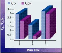 In the first run of 100 parts, conducted over a short period of time, temperatures were held reasonably stable. Ambient temperature rose by
just 0.9�C (1.6�F) during the test. In the second run, the same 100 parts were measured while ambient temperature gradually increased by 5�C (9�F), greatly affecting true process capability. Temperature compensation So what's the solution for temperature variation's
detrimental effect on accuracy? Temperature compensation. Temperature compensation systems consist of a microprocessor-based controller equipped with temperature sensors
and a selection of I/O ports. They communicate with electronic gaging systems over analog or digital interfaces. Their temperature sensors are designed to be attached to the
gage fixture to monitor the temperatures of the part being measured, the gage fixture and the calibrating master or masters during gaging operations.
These temperature compensation systems can be programmed with the effective expansion coefficients of the gage, part and master. During measuring operations they
continuously sense temperature variations and compute and send a correcting signal to the gage in real time. The gage then displays the correct measurement after eliminating thermal errors. The dramatic improvement obtained by using automatic temperature compensation is shown in the results of the third run in Figure 3. In the final long-term run, temperatures
were again allowed to rise by 5�C (9�F) while the same 100 parts were being measured, but in this case, temperature compensation was applied. Figure 1 also shows the
difference between a temperature-compensated and a noncompensated system. These results were obtained from a regular shop floor post-process precision gage operating in
a typical shop floor environment. Many such gages have successfully been adapted with temperature compensation systems to obtain similarly improved results.
Temperature compensation systems have routinely been installed on automatic, benchtop and hand-held gages over the past several years. Albion Devices Inc. of Solana
Beach, California, has recently begun to install systems on in-process gages for applications such as grinding. These systems sense the temperature of parts and
in-process gages during the machining operation and provide a correcting offset to the gage. The result is that dimensions are measured as if temperatures were being
controlled at reference temperature (20�C/68�F) even though operating temperatures are considerably different. However, because the system displays the size that parts would
be if they were at reference temperature, they can be machined directly to final size without the need to allow time for cooling before making final measurements and performing a finishing grind.
Improving quality and process capability
By turning a blind eye to the issue of temperature, you can miss a valuable opportunity to improve quality and process capability. As tolerances become increasingly tight, even
a small temperature variation from the ISO standard will cause significant gaging error. It's easy to be fooled into thinking that you don't have a problem simply because the
measurements are consistent, but nicely grouped data isn't necessarily accurate. As a repeatable gage drifts with temperature, it will continue to give
the appearance of giving good results. We tend to believe what the indicator or the gage display shows, but even though the data may be grouped tightly, it can still be
considerably off target. Don't be misled. About the author
Paul Sagar is president of Albion Devices Inc. ( www.albiondevices.com ). E-mail him at psagar@qualitydigest.com
. |