by Belinda Jones
To-Do List for Servicing Mission 4
One thing you can say about the Hubble is that NASA is squeezing out of it every ounce of data that it can before the telescope is deorbited. With more than 17 years of historic and trailblazing science already accomplished, Hubble will be reborn with Servicing Mission 4, most likely the final manned mission to the telescope. The mission will feature the installation of two new cutting-edge instruments to enhance the Hubble’s capabilities by large factors, the refurbishment of the Hubble’s subsystems, and the extension of its operating life to at least 2013. Astronauts will also attempt the first-ever on-orbit repair of two existing instruments--the Space Telescope Imaging Spectrograph and the Advanced Cameras for Surveys. Servicing Mission 4 was originally planned for 2004, but was postponed after the Space Shuttle Columbia tragedy in 2003 and then canceled in light of safety concerns. Following the successful resumption of the Shuttle program and a re- examination of Servicing Mission 4 risks, NASA approved one last servicing mission. The reinstated Servicing Mission 4 is currently scheduled for flight in August 2008. The tasks of this mission are as follows:
Source: NASA
(http://hubble.nasa.gov/missions/sm4.php and www.nasa.gov/pdf/206048main_SM4_Summary.pdf)
|
Install Wide Field Camera 3 (WFC 3)
|
A high-resolution/wide-field camera with continuous coverage of wavelengths or colors of light from the ultraviolet to the near-infrared |
Install Cosmic Origins Spectrograph (COS)
|
The most sensitive ultraviolet spectrograph ever planned to fly on the Hubble |
Repair STIS
|
Restore the Space Telescope Imaging Spectrograph to operational status |
Repair ACS
|
Restore critical scientific functionality to the Advanced Camera for Surveys |
Replace rate sensor units (gyroscopes)
|
Complete change-out of all six gyroscopes, the heart of the telescope’s pointing system, and the Hubble’s main wear-out items |
Fine Guidance Sensor (FGS)
|
Last in a series of changed-out units that allow fine pointing of the Hubble |
Replace batteries
|
Replace the six batteries originally launched with the Hubble in 1990, which are steadily losing capacity as they age |
Install soft-capture mechanism |
Install the soft-caputre mechanism on the aft end of the Hubble to aid autonomous rendezvous and capture of the Hubble in a future mission |
New Outer Blanket Layers (NOBL) |
Install the remaining three NOBLs to thermally protect equipment bays whose thermal insulation has been degraded by the environment in space
|
When NASA comes to mind, one instantly envisions its mission to launch vehicles to the moon and beyond. Yet the agency has a secondary mandate: Whatever NASA puts into low Earth orbit must be safely brought home upon its expiration date. Such is the eventual case with the Hubble space telescope.
Launched in 1990, the Hubble has broadcast more than 750,000 celestial images, and has been a major contributor to modern astronomy and space exploration, despite some early embarrassing setbacks. With a life expectancy of 20 years, the scientific community speculated that the Hubble would fail in the next few years without repairs. So after years of deliberation and public outcry to save the beloved Hubble, NASA announced a fifth and final Shuttle-to-Hubble mission.
The seven-astronaut crew of Servicing Mission 4 will conduct the last restoration of the observatory in September 2008. This extreme makeover will buy the space observatory more time, resetting its retirement to 2013. Meanwhile, the telescope’s ultimate destiny is still being hashed out by NASA. Based on extensive analysis, the agency concludes that the Hubble is unlikely to reenter the earth’s atmosphere on its own before 2020. Preparations for the eventual deorbit of the telescope are underway at NASA Goddard Space Flight Center in Greenbelt, Maryland.
The Hubble resides 353 miles above the Earth’s surface; interestingly enough, the 13-ton observatory does not have a propulsion system. NASA is devising a plan that will autonomously link up its new shuttle or other robotic vehicle with the telescope, add the necessary propelling force, and thrust it back toward Earth. Destination: an uninhabited stretch of the Pacific Ocean.
For a spacecraft, manned or robotic, to dock safely with the Hubble, it needs a way to measure how far away the Hubble is and how the Hubble is oriented relative to it (also known as “pose and position”). Normally, the sensors that make these kinds of measurements measure the distance and orientation of a special target mounted on a spacecraft. The Hubble has no such special targets. The following article describes how NASA engineers plan to retrofit the Hubble so that real-time measuring of its position and orientation in space is possible, thus enabling automated docking .
Although a deorbit module project for the Hubble has been canceled, the quest for sensor technology and the creation of an attachment fixture has continued full speed ahead. The fixture will be outfitted to the end of the telescope during Servicing Mission 4.
Aligning and mating two moving objects in space is no small task. NASA engineers have proposed a theoretical vehicle-alignment and part-mating methodology designed to systematically connect the Hubble with another spacecraft. To prove out the concept, a team of experts recently gathered at NASA Goddard for a trial run of its groundwork in sensor technology.
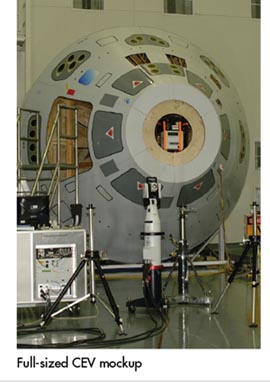
The test was made up of five key components: robot, soft-capture mechanism (also called an “attachment fixture”), crew-exploration vehicle (CEV), space-certified sensor technology, and a laser tracker with a wireless probe. At one end of a clean room, the attachment fixture was mounted onto a FANUC robot, which moved the fixture in a floating space- replicating motion. At the opposite end of the clean room was a full-sized CEV mockup positioned on its side (as seen in the image on page 21). Just inside the vehicle’s opening were three different sensor systems used to locate the fixture and provide positioning data to align the CEV with the Hubble’s attachment fixture. Finally, to the left of the CEV was a Leica laser tracking system used to verify that what the navigation sensors seemed to be detecting was really what was happening.
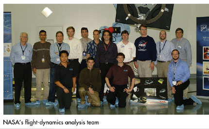
Bo Naasz, NASA aerospace engineer at the flight dynamics analysis branch, led the weeklong endeavor. Naasz and other team members worked several long days in the simulation environment. Representatives from NASA, FANUC Robotics America Inc., Leica Geosystems, Neptec Design Group, Ball Aerospace & Technologies Corp., and Advanced Optical Systems Inc. offered their expertise for the duration of the exercise.
“The testing being done is laser imaging of the soft-capture mechanism, which will be installed on the Hubble during Servicing Mission 4,” says Naasz. “The soft-capture mechanism has retroreflectors and a LIDS [low-impact docking system] adapter on it. The objective of our work is to make the next rendezvous with the Hubble easier. In the past, our Hubble encounters were made with the Space Shuttle, and Servicing Mission 4 may be the last time we go back to the telescope with the Shuttle. We believe a final rendezvous with the Hubble will occur as NASA safety requirements necessitate that we park it somewhere in the South Pacific Ocean.
“In anticipation of this event, this week of testing was all about demonstrating our ability to estimate relative position and relative orientation of our suite of sensors to the soft-capture mechanism.”
To conduct the test, the team mounted the soft-capture mockup onto a FANUC robot, which provided limited six-degrees-of-freedom (6DOF) motion to move the target around, simulating the movement conditions that a docking craft might encounter when approaching the Hubble. As it was being moved around, the mockup was imaged with three different engineering prototype relative navigation sensors that will be mounted to the docking craft to help guide it into position with the Hubble. A Leica LTD840 laser tracker was used to provide “truth information” for the relative positioning and orientation, comparing the data from the sensors to the actual data collected by the laser tracker to determine how well the sensors performed.
“We are trying to gain as much expertise as we can with these technologies and the target we will ultimately use for the last Hubble rendezvous,” explains Naasz.
The three sensing technologies being evaluated offer unique approaches to pose-and-position measurements, rendezvous and docking issues, and orbital proximity operations. Neptec’s TriDAR integrates a dual-sensor 3-D scanner and a full-pose (6DOF) docking sensor. Ball Aerospace demonstrated the capabilities of its 3-D flash-imaging laser detection and ranging (LIDAR) system providing real-time target topography. Advanced Optical Systems presented its Advanced Video Guidance Sensor, which uses laser light to illuminate retroreflective targets and then uses the return light to compute 6DOF information.
 Requirements for measurement validation and data redundancy were also factored into the test program with the use of the high-precision Leica laser tracking system. The portable coordinate measuring machine provides a measuring rate of up to 3,000 points per second, with a measurement range of up to 40 meters (131 feet). Based on a high-speed tracking 3-D laser interferometer and precision angular encoders, the laser tracker enables scientists and manufacturers to capture 3-D coordinate data on demand, perform alignments and part mating, confirm close tolerance work, conduct complex assemblies, and more. Requirements for measurement validation and data redundancy were also factored into the test program with the use of the high-precision Leica laser tracking system. The portable coordinate measuring machine provides a measuring rate of up to 3,000 points per second, with a measurement range of up to 40 meters (131 feet). Based on a high-speed tracking 3-D laser interferometer and precision angular encoders, the laser tracker enables scientists and manufacturers to capture 3-D coordinate data on demand, perform alignments and part mating, confirm close tolerance work, conduct complex assemblies, and more.
The laser tracker works in tandem with a Leica T-Probe, a wireless 6DOF tracking device for automated applications. The wireless probe has a point rate output of 1,000 points per second, a measurement volume of up to 30 meters (98 feet), and an ultra-wide acceptance angle: pitch ±45°, yaw ±45°, roll 360°. The probe has a single retroreflector so that the laser tracker can track its position, and the 10 LEDs on its surface are registered by the tracker’s camera to track its orientation in space. Insensitive to environmental light, the device delivers a two-sigma length measurement accuracy of 60 µm in a measurement volume of 15 meters (49 feet).
The T-Probe was mounted securely to the soft-capture mechanism and was used to measure dynamic 3-D motion data (x,y,z, pitch, roll, and yaw) as the robot moved the attachment fixture randomly in space. During the test cycles, precision data was captured by the device to be used later to validate measurements simultaneously gathered by each of the three sensor systems.
Presiding over the laser tracker operations was Brent Barbee of Emergent Space Technologies Inc., headquartered in Greenbelt, Maryland. Barbee used two software programs-- SpatialAnalyzer (New River Kinematics, headquartered in Williamsburg, Virginia) and a specialized software program developed for the laser tracker at NASA’s Marshall Space Flight Center--to interface with the tracker and give continuous time-stamped measurements of the T-Probe’s orientation in space.
Once the testing is concluded, the arduous task of post-processing the data gathered from the test cycles must be tackled. Barbee has written a script to translate the Leica “truth data” into the coordinate frame of the sensors being evaluated. Essentially, they have all the information that they need to compare apples to apples, comparing motion data reported by the three sensor sources under evaluation to the data acquired by the laser tracker.
As of this writing the data analysis is still ongoing. The results of the analysis will help NASA determine which of the three sensor technologies will be used to help dock to the Hubble.
Acquiring motion data is only one of many measurement tasks that leverages the mobility and accuracy of a laser tracker. These portable coordinate measurement machines, theodolites, and noncontact hand scanners are utilized daily by NASA Goddard technicians for a wide range of metrology applications, from general 3-D inspection to component alignment, spacecraft integration, and complex assembly operations.
“We have been in critical situations where we need to get close to flight hardware and there are contamination issues,” explains Henry Sampler, a veteran in the optics, test, and alignment department. “We don’t want people actually touching parts, and noncontact scanning was really the answer to this issue. A good example is the James Webb Space Telescope, where there are cryogenic mirrors and other instruments that affect the focus of the telescope. When it comes to optics, noncontact scanning gives us the ability to gather data about a position or a component very accurately without touching or contaminating sensitive areas.”
With laser tracking technology providing a reality check, NASA moves space projects forward confidently with dimensional control built into each stage of the program. With the ability to troubleshoot, measure, validate, assemble, and mate parts to very low tolerances with a full six degrees of freedom… the sky is nowhere near the limit for NASA Goddard.
Belinda Jones is the founder and owner of HiTech Marketing LLC ( Westbrook, Connecticut). For more than a decade, Jones has written articles and commentaries about manufacturing, engineering, quality assurance, CAD/CAM/CAE applications, and other high-tech topics. She has extensive experience in marketing communications, technical sales, and applications engineering. Before joining the computer industry, she was a broadcast copywriter for four years. Jones holds degrees in fine arts and mechanical engineering, and studied cultural arts in Europe.
|
