by Ken Steffey and Chuck Pfeffer
At rare moments, an idea comes along that makes people rethink how a job is done. The engineers at Falk PLI Engineering and Surveying have hit on such an idea for one of the most basic concepts of all: dimensional measurement. They have built their business around the notion that for machine alignment, it's necessary to move beyond three-dimensional analysis to include a fourth dimension: time. This concept recognizes that measurements are only correct for the conditions under which they are taken.
Emerging as one of the most significant players in dimensional verification of metalworking processes—particularly steel—this Portage, Indiana, company demonstrates the truth of this concept all over North America. From coke plants to pickling lines, the larger-than-life nature of steelmaking would seem to belie the need for precision. But primary forming processes such as raw slab, billet or bloom stock depend on tight dimensional tolerances. During the secondary forming process, hot rolling and cold rolling steel require even tighter dimensional control. Precise alignment of primary molding and secondary shaping equipment is critical for optimum throughput because the cost of yearly scrap from these lines can reach tens of millions of dollars.
Composed of more than 30 engineers, Falk PLI Engineering and Surveying is led by Mike Falk. For more than two decades Falk has studied the science of measurement and been associated with a number of massive construction and alignment projects, including the huge superconducting super collider that was assembled on a 54-mile circumference near Dallas during the late 1980s. Early in his career, Falk began to notice that actual machine dimensions were not always what they were purported to be on drawings. The challenge was to help original equipment manufacturers in the steel industry achieve better product quality, higher throughput and less downtime in the field as they reassemble massive equipment components to precast mounts.
Machine elements shrink and grow due to changes in temperature. Everything in the world moves; it's simply a matter of why, when, where, how and how much. Even the act of transporting machine elements can change their dimensions. Compounding the problem, the equipment may not have been built using precision measuring equipment. During field assembly, this "dimensional delta" becomes a major headache for machine riggers trying to get the final alignment right.
"These errors are additive, and we have seen a coke plant, caster or rolling line be off significantly from what the drawings said the dimensions were," says Falk. Equipment already in service experiences a similar but slightly more complex problem. Not only does it undergo thermal expansion/contraction, but also dimensions shift due to heavy usage—a fact of life in most metal-forming processes.
Falk has seen the equipment installation area within a steel-casting building grow and shrink by more than 40 thousandths of an inch in 24 hours because of sunlight. Tides and other water phenomena can also affect the shape of a steel mill floor and the alignment of the thousands of tons of forming equipment that sit on top of it. "I can see seasonal differences and even tell which way the wind is blowing on Lake Michigan," he explains. "When the wind is blowing from the north, the water level on the shore can increase by two feet. This causes the water table to rise. The resulting increase in hydrostatic pressure raises the floor and moves any control monuments embedded in, or attached to, the floor."
So when it comes to critical equipment alignment, faster is better. The more quickly measurement can be done, the more quickly equipment can be installed and aligned, mitigating long-cycle environmental effects. The more closely aligned equipment is during initial installation, the less time is needed to fine-tune the alignment, meaning less downtime.
Falk concluded that machine alignment was beyond a three-dimensional problem and began to incorporate time into the analysis.
"Years ago, alignment was seen, at best, as a two-dimensional problem," says Falk. "The surveyor would use optical equipment to perform anchor bolt verifications. But now we know that machine components have a 3-D spatial relationship and, further, that alignment must be done in a reasonable period of time to ensure good fits with the mating equipment. This is the only way to confirm that the sections of a machine work together smoothly and meet product specifications." Optical systems prove to be more labor-intensive and less accurate in handling the third and fourth dimensions.
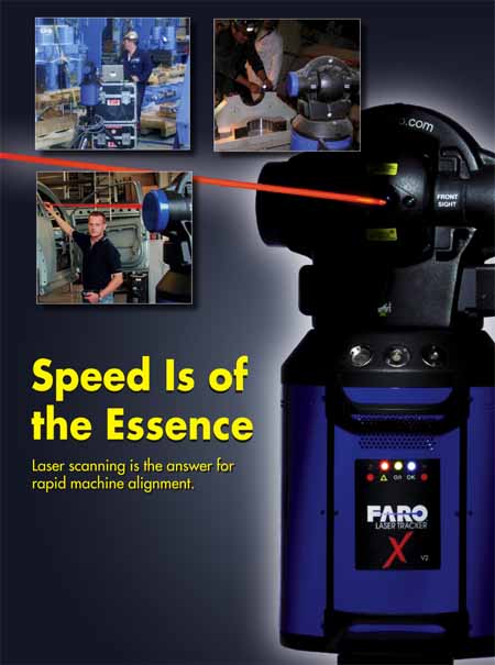
With this in mind, survey consultants who align casters, rolling lines or processing lines must work thoroughly—and fast. Several years ago, Falk's work at the superconducting super collider introduced him to the FARO Laser Tracker, which bounces a beam off a movable spherical retroreflector target and then automatically calculates the position of the target to a 3-D single-point accuracy of 0.001 in. The system can be set up on a tripod in almost any manufacturing environment and gather data in a matter of minutes, in temperatures that range from –15°C to 50°C (5°F to 122°F).
Operating speed is no limitation—the instrument makes 10,000 samples/sec. The tracker ensures that data collection is smooth by visually tracking the motion of a retroreflective target held by an operator or mounted on the device to be measured. If a pillar, motor or other obstacle interrupts the beam, the tracker easily reacquires it and data gathering continues. The niche for this system is using its thousandth-inch accuracy to measure huge objects within a 230-foot range.
During a survey, data collected by a laser tracker is processed by a computer and compared to CAD drawings of the equipment. Locations of out-of-specification bolt holes, pins or machined surfaces are noted on the computer's display, enabling Falk engineers to recommend a course of action to bring the sections into alignment.
Sometimes with older equipment it is more expedient to find a "best fit" for machine sections.
"Equipment dimensions change with age—bearings can become pitted, or even the foundations become soft—and occasionally we find that the best alignment is one that takes into account the relative position of the adjacent equipment, as opposed to resetting everything to the plan schematics dictated by some offset baseline," says Falk.
Laser trackers have allowed Falk to do the same work in less time and with more accuracy. Using optical tooling, Falk's competitors take from 36 to 72 hours for some jobs. All the while, the equipment and environment expand and contract due to temperature and other factors. The same job takes Falk just a few hours, and due to measurement speed, the accuracy has increased from a final accuracy of roughly 0.060 in. with optical tools to about 0.005 in. using the tracker.
Alignment is not the only use for tracker data, however. It can be downloaded into a number of other types of software, including rendering, architectural or CAD programs. In some cases, Falk customers use this information to develop their own custom programs. One customer even won a reliability and maintenance excellence award for a program written by Falk that enables the client to quickly compute the thickness of bearing shims needed for a casting line.
The quality of an alignment depends on thoroughness, and survey time greatly affects project costs. Because a laser tracker gathers data so rapidly, Falk engineers are able to compress projects. Projects that normally take from eight to twelve hours to gather data with optical equipment can often be handled by a tracker in under one hour.
"From our standpoint, this instrument allows us to bid on jobs that otherwise would be too pricey for our customers," explains Falk. "From our customers' standpoint, it allows them to improve their risk management of equipment in an industry where scrap is very costly."
Although the company has measured a wide range of web-type production equipment—from paper mills to aluminum lines—its specialty remains steel casters. Falk has aligned more than 200 of them in just the last three years.
A steel caster allows molten steel to be poured into the top of a mold and to be continuously cast as a long slab of steel out the bottom of the mold, much like when you extrude children's modeling clay out of a press in the form of a square. To say casters and their components are huge is an understatement. Figure 1 below shows a simple drawing of a caster. To get an idea of the size, each of the nine caster segments is about the size of two SUVs stacked on top of each other. Each of these components needs to be aligned within a few thousandths of an inch.
Recently, at an older mill, Falk helped mill operators dramatically reduce downtime during an outage. Working on the mill floor, engineers positioned their laser tracker in the caster and ran the instrument's calibration routine, which takes about five minutes. Then they began collecting data on the caster bow frame, which has a radius of approximately 50 feet. If the owner had been using optical measuring equipment, the survey would have taken anywhere from one-and-one-half to three days. Using a laser tracker, Falk technicians collected the needed measurements in less than two hours.
The results of an earlier survey using optical measurement techniques had been a little unsettling. According to the optical survey results for the caster, all 36 of the bearing pads on which the nine segments sit in the bow frame needed to be adjusted. This is where experience and the versatility of the laser system came into play. Using the laser tracker, Falk engineers showed that only 24 of the 36 bearing pads needed adjustment. Falk engineers took this reduction one step further. Using a "best fit" alignment for the equipment, only seven of the bearing pads had to be adjusted.
"This way, they avoided having to re-shim 29 bearing pads and cut several hours off the outage," says Falk.
Tracker technology has also allowed Falk to measure parameters that were impossible to measure before. For instance, Falk uses the tracker to measure the deflection of the tension reel on which the finished rolled metal is coiled. By placing a reflector on the winder's horizontally aligned axle, it is possible to see that the axle droops toward the floor as the weight from the steel increases, and also deflects laterally depending on the tension of the metal feeding into the spool. Such deflections cause the spools to coil unevenly, leading to costly rework down the line.
Using laser trackers, Falk is able to accomplish a critical steel- mill alignment function in a fraction of the time it used to take, and with ten times better accuracy. The result is less downtime and less waste due to improperly formed product. These savings are critical for an industry that's fighting a tough battle against foreign competition.
"Right now the steel industry is going through a lot of pain," Falk explains. "Here in the United States, business is hurting. We can't compete with China or Mexico on cost alone. But we can help owners be competitive by using talent and technology to create a superior product."
Ken Steffey began his FARO career as a customer support specialist in 1994 and was soon appointed the director of customer training. He became an applications engineer solving on-site metrology issues for top clients, including Boeing's Seattle operation. Steffey also served as director of software development as well as FARO's director of learning before assuming his current role as director of laser tracker product development.
Chuck Pfeffer has 12 years of metrology experience, starting as an applications engineer in Spatial Metrix's (SMX) contract inspection group in 1994. He later handled its geometric dimensioning and tolerancing software development and consulted as an application support specialist. In 1998 he was appointed aerospace systems manager, where he met Steffey while working with him on projects for Boeing. In 2002 FARO Technologies purchased SMX, and Pfeffer became product manager for the FARO laser division.
Visit FARO at CMSC booth Nos. 201, 202, 301 and 302.
|