|
|
|
Today's ever-increasing demands on the manufacturing sector to improve product quality have made coordinate measuring machines the backbone of company quality departments. Surprisingly, many buyers wrongfully believe that all CMMs are the same, and thus find themselves stuck with equipment that fails to meet their inspection needs, much less improve their overall quality. Because of CMMs' growing importance to the entire manufacturing function, extensive thought and planning must go into each purchase. The basic CMM is comprised of four components: the machine itself, the probing system, the computer system and the measuring software. Most companies know what to look for these days in a computer system, but what important factors should you consider when evaluating CMMs, probes and software? The following information should help you select a system that's right for your company and for your particular application. CMM hardware If you want to invest in a quality product that will stand the test of time, don't skimp on the quality of the machine hardware. Be sure to consider these points when evaluating CMM equipment:
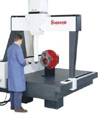
Many companies make these components out of aluminum because of its light weight, machinability and relatively low cost. However, materials such as granite or ceramic are much better for CMMs because of their thermal stabilities. In addition to the fact that aluminum expands nearly four times more than granite, granite has superior vibration dampening qualities and can provide an excellent surface finish on which the bearings can travel. Granite has, in fact, been the widely accepted standard for measurement for years. For CMMs, however, granite has one drawback-it's heavy. The dilemma is to be able, either by hand or by servo, to move a granite CMM around on its axes to take measurements. One organization, The L.S. Starrett Co., has found an interesting solution to this problem: Hollow Granite Technology.
Probing systems Once you've found the right CMM, you should select a probing system. Most CMM manufacturers use Renishaw for their probing systems. Renishaw's product quality and accuracy are exceptional in the industry. Selecting a probing system that is most appropriate for your particular application is more involved than simply picking one out of a catalog. You must first have a good understanding of the components that make up a complete system as well as each component's features and benefits. The basic Renishaw probing system consists of three main components: the probe head, the probe and the stylus.
Nonarticulating probe heads allow only one probe orientation-straight down. When inspecting cube-shaped parts, you may be able to get by with a nonarticulating probe head if you use a "star" stylus on the probe. This stylus gives you a cluster of up to five styli, pointing forward, back, left, right and down. While you should be able to measure all of the cube's features, keep in mind that this works for only the simplest of part configurations. Nonarticulating probe heads also are used extensively for measuring features machined or stamped into flat sheet metal or on any parts that only need a straight-down probe orientation. They can be used on both manual and DCC machines. Articulating probe heads enable the operator to point the probe in many different directions. Renishaw uses two angles to control the direction that the probe points-the "A" angle, which is the number of degrees of elevation from the straight-down position, and the "B" angle, which is the direction in the horizontal plane that the probe points. These angles are either in 15-degree or 7.5-degree increments. Probe articulation allows the measurement of features on the back or sides as well as features at oblique angles. Each articulating probe head has a maximum extension length. For example, if you need to reach far down into a bore for a measurement, make sure you purchase a probe head that can support the weight of the required probe extension bar. Articulating probe heads come in two general varieties: manual and automatic. Just as the name implies, manually articulating probe heads require operator intervention to move the probe to the desired orientation. Although these probes can usually be used on both manual and DCC CMMs, keep in mind that, on a DCC machine, the program will stop at each programmed probe change and wait for the operator to walk back over to the machine and articulate the head. Automatic articulation allows the probe angles to be changed automatically from within the part program. Thus, very complex part programs utilizing many different probe positions can be run completely unattended. These probe heads are used only on automated CMMs. If you've already decided to purchase a DCC machine and you need only articulate the probe head occasionally, you're probably better off purchasing a manually articulating probe head. If, on the other hand, you need to articulate the head more than that, you're defeating the purpose of the DCC machine by attaching a manual probe head. An automatic program is of little benefit if an operator must stand there most of the time to change probe orientations.
Probe accuracy depends on the triggering system's design. Renishaw primarily uses mechanical triggering mechanisms (used on the TP-2 and TP-20) and strain-gage mechanisms (used on the TP-200). The strain gage-based probe is more accurate than its counterparts, especially when used with longer styli. If, however, the CMM is near a source of strong vibration, consider the TP-2 or TP-20 to avoid false triggers induced by the vibration. Also consider the system's ability to change the stylus tip automatically within a DCC part program. The TP-2, for example, doesn't have this capability. With this probe, the stylus must be unscrewed from the probe, the new one attached, and the stylus tip recalibrated on the calibration ball. On the other hand, the TP-20 and TP-200 use stylus modules that are magnetically attached to the probe. These can be removed and replaced, either by hand or by using a module-changing rack, without the need for probe recalibration. Using the module-changing racks allows this entire function to take place automatically within a DCC part program, requiring no operator intervention. Other probe types such as video, laser and noncontact may also be useful if the application warrants them.
CMM software Because the machine's overall measurement capabilities and ease of use depend almost entirely on the inspection software, don't let your evaluation of this component be limited to how flashy the user interface appears. You may not know the software's true capabilities unless you ask. Also, think about future needs. Buying a system that barely handles your current requirements would be a mistake in this ever-changing industry. At a minimum, make sure you evaluate the following 15 characteristics before you decide which system is right for you: 1.Ease of use. Simple measurement tasks should be easy, obvious and intuitive. Additionally, the software should be easy to navigate, and a good online help system is a must. 2.Nonconventional part alignments. Virtually all CMMs can handle simple part alignments like plane, line and point. But what about more involved alignments like offset datum planes or datum target points on complex surfaces? Though you may not need these features today, a blueprint may come through your shop tomorrow that requires them. 3. Complex surface measuring. CMMs can easily measure simple geometric shapes like circles, lines and cones. Measuring and evaluating complex surface shapes like airfoils, valve heads or bicycle helmets is an entirely different matter. Good CMM software will provide a mechanism to collect data on these features using a CAD surface model of the part. It should also allow you to create section lines on the surface to measure. 4.Automatic feature measurement. This function allows the CMM to automatically move to a defined feature and take the measurement points on it. This can facilitate programming a DCC CMM. Typically, the operator defines the geometric feature by keying in the nominal information or by clicking on the feature in a CAD model. Software without this ability must rely on the operator to program the probe motion and measurement points using only the joysticks. 5.Scanning of unknown geometries. This allows a feature or complex surface to be scanned for data without knowing its nominal definition. On automated machines, the operator typically probes the start and end points for the desired scan and specifies a scanning density, allowing the CMM to "learn" the contour in between. 6.Programming language. Good CMM software uses a powerful yet easy-to-read programming language. While some companies use their own proprietary languages, you can instead acquire inspection software that uses the dimensional measuring interface standard, the industry standard programming code for CMMs. This will allow interchangeability of part programs between different brands of DMIS-based CMMs. 7.Geometric tolerancing. All types of geometric tolerancing should be available in the CMM software, including line and surface profiles. 8.CAD interface. Not only should the CMM software accommodate multiple CAD file types, it should also present that information in a clear and understandable manner on-screen. Ideally, it should allow the user to control the graphical representation (such as wireframe or surface) and to group and hide various features for visual clarity. 9.Offline programming. To get the most throughput from a DCC CMM in high-production situations, the CMM should run part inspections as much as possible. In order for this to happen, there must be a way to write CMM programs without actually utilizing the machine itself. Look for CMM software that enables you to write your programs easily offline using a CAD model. Ideally, you should be able to download a program from an offline workstation into the CMM and have it run with little or no editing. 10.Outstanding reporting capability. All CMMs have some way of printing out inspection results in at least a tabular format. Instead, look for a software with which users can customize the output to their own specifications. The software should also incorporate graphics into the reporting for better understanding of inspection results. 11.Graphical feature analysis. Make sure the CMM software can graphically compare measurement points to the known CAD definition. This helps immensely in visualizing the part's entire dimensional condition. 12.Integrated best fitting. Best fitting mathematically "shakes" the part to find a position where most or all features will come into tolerance. This also allows line and surface profiles to be checked relative to themselves (with no datum reference). Verify that the CMM software allows you to specify any combination of features for inclusion in the best fit and any combination of axes to translate along and rotate about. This is essential to seriously evaluate the entire manufacturing process. Often, best fitting comes only as a third-party package on an offline computer system. Far superior, however, is CMM measuring software that directly integrates best-fitting capabilities. 13.Integrated statistics. As with best fitting, find a system that integrates statistics into the inspection software, eliminating the need to dump data into another system. Ideally, you should be able to incorporate these stats into the inspection report. 14.Reverse engineering. This process creates a CAD definition of an unknown or modified part. To do this, the software must be able to export your measured feature data to a file format that your CAD system can read, such as the initial graphics exchange specification (IGES) format. 15.Support of optional equipment. Verify that the CMM software supports equipment such as stylus-changing racks or rotary tables. You may wish to add this equipment sometime down the road. A demanding industry Don't forget accuracy when evaluating a CMM. Accuracy requirements depend primarily on the tolerancing of the parts to be measured. Linear accuracy, as the name implies, is an accuracy reading for each axis independently. Remember, however, that each machine axis must be built mutually perpendicular to the other two. Therefore, volumetric accuracy better represents a CMM's true overall accuracy. Today's manufacturing industry is filled with ever-increasing demands for improving product quality. CMMs, once found in only the largest companies, are now being used by virtually all types and sizes of companies across the entire manufacturing spectrum. Because of the critical role CMMs play, serious thought should go into evaluating the machines before committing to a purchase. After all, the quality of your products depends on it. About the author Steve Meredith is western region sales manager for The L.S. Starrett Co.'s CMM Division in Glendale, Arizona. Telephone (602) 915-1111 or e-mail smeredith@qualitydigest.com . |
| [QD Online] [Choose CMM] [CMM Guide] [CE Mark] [weibull] |
|
|
|
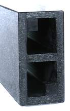 This technology uses solid granite plates and beams that are manufactured and assembled to form hollow structural members. These hollow structures weigh like aluminum while retaining granite's favorable thermal characteristics. Starrett uses this technology for both the bridge and bridge support members. In a similar fashion, they use hollow ceramic for the bridge on the largest CMMs when hollow granite is impractical.
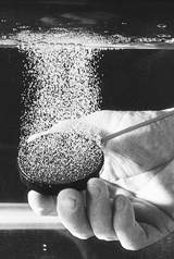 However, air bearings also have their inherent differences. Ideally, look for a system that uses porous graphite as the bearing material instead of aluminum. The graphite in these bearings allows the compressed air to pass directly through the natural porosity inherent in the graphite, resulting in a very evenly dispersed layer of air across the bearing surface. Also, the layer of air that this bearing produces is extremely thin-about 0.0002". Conventional ported aluminum bearings, on the other hand, usually have an air gap between 0.0010" and 0.0030". A small air gap is preferable because it reduces the machine's tendency to bounce on the air cushion and results in a much more rigid, accurate and repeatable machine.