by Dirk Dusharme
Laser projection systems for manufacturing assembly have been available since the early 1990s. The first systems were used primarily for aligning materials during composite layup--replacing both Mylar and fiberglass layup templates. They were also sometimes used for parts alignment or placement verification on finished assemblies. For instance, a projected laser template would show the fabricator exactly where to mount a bracket, position a paint stencil, or drill a hole.
Essentially a glorified laser-light show, the concept has always been fairly straight-forward: A CAD model provides coordinates to the laser projection system, which then uses mirrors to precisely steer the laser and draw the template. Because the laser is scanned quickly, the lines in the projected image look solid.
Although early systems could reduce the time for some production operations by as much as 80 percent, they still required a certain amount of manual labor because the projected template had to first be aligned with known points on the work piece before it could be used. The standard approach in many earlier systems (and some existing systems) is to attach tooling balls or reflective targets to known points on the work piece. The operator then manually points the laser beam at each of these targets, getting the beam to within a few inches of the target. That is close enough that the projection system can then automatically scan the immediate area, detect the reflection from the target, and locate the target center. The operator does this for a half-dozen targets. Once the targets are acquired, the software has enough positional data to align the template to the work piece with a high degree of accuracy, typically about 0.015 in.
Although this method was much faster than other templating techniques, it was still clunky, and only the operator’s eye determined how closely they had aligned a part to the template. Even the best-trained eye can only get to within about 30 or 40 thousandths of an inch accuracy. Today, advancements in laser projection systems allow for hands-free, unassisted alignment. Along with faster and more accurate templating, this new technology also provides unique capabilities for part measurement, assembly verification, highlighting areas requiring rework, and reverse-engineering and fabrication.
A standard laser projection system already has at least one-half of what’s required for a 3-D laser radar measuring system. You have the laser, a precision laser-steering mechanism, and a means for detecting a reflected beam. Improve on those capabilities and add the ability to measure distance, and you have a new breed of laser projector, one that can also perform large-volume, hands-free, 3-D laser scanning. Laser Projection Technologies, of Manchester, New Hampshire, is the first company to create a hybrid laser projection device capable of high-speed, 3-D laser scanning.
Recent technological advances have enabled the company to produce the LPT 100, a laser radar/projector capable of measuring 100,000 points per second with an accuracy of 250 µm at five meters. Although the accuracy doesn’t compare with a gimbaled laser-radar system, such as that produced by Metris, it is about 100 times faster. Plus, it’s still a projector. It’s this combination of laser radar and projector that has created a unique market niche for the company.
The LPT 100 has some advantages over laser trackers or other laser radars for assembly operations. First, unlike laser trackers, it doesn’t require the user to walk around a work piece with a spherically mounted retroreflector (SMR). Second, its tremendous speed sets the LPT 100 apart from other laser radars. This speed is largely due to the way that the beam is steered. Traditional laser radars or laser trackers use a gimbaled system to steer the laser beam. Gimbaled systems use very precise X and Y motors with linear encoders to move the laser steering mirror. Although accurate, the mass of the mirror and gimbals limit the speed to which they can be moved, thus limiting scanning speed. Projection systems use galvanometers in the X and Y axes to deflect a small mirror and steer the laser. The mass of this system is miniscule compared to a gimbaled system, meaning that the mirror can be modulated quickly, allowing for very fast scanning speeds.
Because of its speed and ability to project, the main application for the LPT 100 is as an assembly verification tool. This is the company’s target market, according to Steve Kaufman, president of LPT. The aerospace, automotive, and shipbuilding industries use laser projection to quickly align parts or paint stencils, for instance, but have had to rely on other equipment for verification. Although laser trackers and traditional laser radars could sometimes accomplish the verification task, they were slow and the accuracy was overkill for that application.
“The main problem is that you can’t do 100-percent inspection of every assembly with five-tenths accuracy,” says Kaufman. “But you can assemble and quickly verify assemblies at a thousandth and then take samples [to measure at higher accuracies].”
Kaufman’s solution was to use the same device for assembly and verification.
“For years we’ve been watching people use our older projectors not only as templating devices but as a way to verify the position of parts, scribe marks, and so forth,” explains Kaufman. “But those were qualitative, not quantitative, judgments. They weren’t actually measuring anything. The accuracy was only as good as the operator’s eye. I wanted to give them a tool that not only helped them to assemble, but also gave them a quantitative verification of what they just did.”
Until recently, Kaufman’s goal wasn’t possible. Although the laser in LPT’s products could be steered very quickly, the technology didn’t exist to steer it as accurately as required or to collect points as quickly as needed for measurement.
“Two years ago the electronics simply were not available,” explains Kaufman. “They were still on the drawing board. Consequently, I’m now competing for the LPT 100’s electronics with places like JPL, Fermi Lab, and the [ UK’s] National Physical Laboratory. The technology is that new. I’m talking about photodetectors that are really fast and specialty, fast analog-to-digital converters.”
The key to understanding the value of the system is in realizing what can be done when you couple a measurement system with a laser projector.
All 3-D scanning systems compare the captured point clouds to a CAD model and display the variance from specification on the operator’s computer monitor.
A laser radar/projector takes this one step further by giving the operator the capability of projecting out-of-spec features directly back to the work piece. Here are two real examples of how that works:
• Missing or out-of-spec feature. An aerospace manufacturer fabricates a large piece of sheet metal that contains hundreds of holes. One hole is missing or out of location. A traditional scanning system would show the error on the monitor, but the operator would have to manually locate the out-of-spec hole or holes on the work piece. A scanner/projector simply points the laser beam at where the hole should be, providing instant visual feedback to the operator.
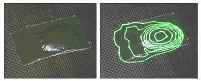
• Topographic display. A large carbon composite panel is scanned and compared to CAD design specifications. The measurement indicates a raised area, or deformity, in the panel. The system projects a topographical representation of the variation onto the piece, allowing fabricators to see the precise outline and magnitude of the deformity, as seen in the images below. The piece is immediately marked and sent to rework.
A recent application saved a large aerospace company dozens of man hours. The company needed to replace the sheet metal skin on a pylon for a jet engine nacelle. At issue was the lack of drawings defining the hole patterns for the fasteners that attach the skin to the pylon frame. That’s because skins are often hand-drilled and assembled. The skin is laid over the pylon framework, clamped in place, and then fastener holes are drilled through the skin and framework together. The end result is a perfect fit--and handmade.
The normal process for putting new sheet metal on the pylon would have been to lay the newly formed sheet metal over the framework, clamp it, and mark the skin through the holes from the underside when possible. When not possible, each inaccessible hole on the frame must be measured from a reference point and that measurement precisely transferred to the skin. For hundreds of holes, this is a job that easily takes several people several days.
In this case, to reverse-fabricate the pylon’s sheet metal, fabricators removed the old skin from the framework and scanned the framework with the LPT 100, creating a CAD drawing complete with the location of the framework’s fastener holes. They then clamped the new sheet metal over the pylon and precisely projected the hole pattern back onto the skin, allowing fabricators to drill new holes exactly where they should be.
Because a laser radar/projector measures the intensity of the reflected beam as well as its 3-D coordinates, the system has very good edge- detection capabilities. This enables the system to more precisely measure parts and, coupled with the company’s proprietary software and third-party point-cloud analysis software from companies like Verisurf, the LPT 100 is able to identify and extract individual parts on a scanned assembly. For instance, from the collected point-cloud data, it could identify a bracket attached to a panel and each of the bolts holding the bracket. Part recognition means that it’s possible to scan not only part placement on an assembly, but also to identify a part and compare the specs of just that part to a CAD drawing.
The LPT 100 is still a projector, of course. But because it is also a scanner, it can measure the complete form of the work piece and compare it to a CAD drawing to determine alignment. There is no longer a need to use targets or tooling balls to align a projected template. The operator places the work piece in front of the projector, the projector quickly scans the piece, performs a best-fit to the CAD model, and then projects the desired template onto the piece for parts assembly, drill patterns, and so forth. Afterward, it can rescan the assembly and verify that the assembler did the job correctly.
Adding laser radar capabilities to a laser projection system opens up new possibilities for large-scale assembly and verification. The biggest interest in this technology is in the aerospace, automotive, and shipbuilding markets that rely heavily on templates for parts placement and alignment. Adding measurement capabilities facilitates in-process inspection of assemblies and quick identity of out-of-spec parts.
Reverse-engineering and reverse- fabrication are more easily accomplished when unknown dimensions can be scanned, transferred to a CAD package, and then projected back onto work-in-progress.
A laser radar/projector hybrid combines the best of both technologies to speed up and improve large-scale assembly operations.
Dirk Dusharme is Quality Digest’s editor in chief.
|