Social Sharing block
In the manufacturing industry, it is ideal to ensure high manufacturing accuracy without the need for inspection. In fact, however, the inspection and the measurement processes are performed for various reasons, such as to secure the product traceability, to visualize the quality of production, and to uncover an aging manufacturing system at an early stage.
|
ADVERTISEMENT |
We developed a 3D measurement system aimed at full automation, with one-touch operation that could be accomplished without experts. This system was originally presented at the Coordinate Metrology Systems Conference (CMSC) in 2010. In developing this system, we built in various recovery functions, guided by the premise that all processes do not work as the designer might assume.
For the purposes of reducing initial costs, we also received a request for a semi-automatic measurement system in which an operator could intervene. A flexible design was required in which the human was considered to be one component in the system, and we needed to clarify the division of roles between a system and a human. Flexibility was important because the division of roles would change during the course of time.
Three key points were taken into consideration during the development of the system. First, we needed to clarify the division of roles between the operator and the measurement system. We determined that the operator makes selections, establishes settings, and inputs data; checks the information that is input into the system; directs the overall system; and takes actions for follow-up steps. The measurement system exists to take action according to the operator’s directions; to start or stop the relevant actions according to the operator’s selections, settings, and data inputs; to support the operator’s judgments and actions; and to display the required information.
Second, we considered the efficiency of the design in the planning phase so that an operator unfamiliar with the system could easily understand the nature of the system, the kinds of operation that should be carried out, and the types of screens based on specific forms of information. We designed the system to be flexible in coordinating the correction requests for the human machine interface (HMI) as well as the processing. In working toward a foolproof design, it was considered necessary to make the interface screen quite simple, and not permit unusual operations to be easily carried out. However, we also considered a design which would not pose a problem even if it should be necessary to carry out unexpected operations.
Third, we investigated reliable test methods, taking into account once again that the operator might perform unexpected operations. We developed a 3D measurement system by which operators could intervene, and the design efficiency and the quality of the measurement system were greatly improved. Further, the change request of the HMI after the completion of the system was built into the minimum operating requirements. The instrument of this measurement system is Nikon Metrology Inc.’s Laser Radar (LR), which has the ability to handle large-scale, noncontact precision measurement as is necessary in the aerospace industry and other various sectors.
This article describes how we developed this 3D measurement system.
Introduction
Hitachi Power Solutions has developed an automatic 3D measurement system aimed at improving productivity and used in the aviation, railroad vehicle, iron, steel, electricity industries.
Figure 1 shows the position of the measurement process within general production. In the factory, 3D measurement is performed in the alignment before machining, dimensional inspection, assembly, and the final inspection processes. The surface measurement is performed after machining to inspect the processed products. Measurement is critical not only as a final inspection, but also in terms of judging the correctness of the process. The measured data are used for reprocessing if necessary. The feedback information obtained by 3D measurement is important for improving the performance of the processing machine and overall production efficiency. If a change in the accuracy of a processing machine is detected at an early stage, it can help greatly reduce relapse work such as corrections and/or reproductions. Therefore, it generates a huge effect by improving the product quality and efficiency of the entire production process. There are increasing demands on the automatic measurement in accordance with the extension of automation in the production line. When we consider the design of the automated process, whether in production or measurement, it is necessary to continue planned automatic operations as much as possible, even when a part of each subsystem or subprocess cannot operate normally. Therefore, in most cases, the system should be equipped with various recovery functions in the system design phase.
On the other hand, there are the following problems in such an automation system:
• Because it is an advanced system equipped with many recovery functions, it becomes expensive
• In some cases, recovery functions take more time than skillful manual operation
• Once an advanced automation system is built, the flexibility is lost and the usual operator cannot solve problems which may have occurred in the system
From these reasons, a request was also made for a semi-automatic measurement system in which operators are able intervene. Therefore, we developed the measurement system enabling the operator’s intervention at key points. In the development of such a system, a design is required in which the human is considered to be one component of the system, and the clarification of the division of roles between the human and the system is critically important. Moreover, because the human’s division of roles also changes through progress of time, flexibility is required of the system. These points are described next, which should be taken into consideration regarding the design of a system in which operators are able to intervene.

Figure 1: 3D measurement in production process
Design concept for semi-automatic measurement system
The following points which should be taken into consideration when designing a general measurement system:
• The purpose of the measurement
• The type of object and the portion of that object to be measured
• Required specifications
• The person who will perform the measurement
• How and where the measurement results are to be used, remembering that output data format should be suitable for the appropriate section
• When the measurement is to be performed, remembering to clarify how much time could be taken in the field
• Where the measurement is performed, remembering constraints such as measurement space
• How the measurement will be performed, remembering the measurement method and the reason for the selected method
• The estimates of the initial costs and the running costs
Considering the above-mentioned points, the user should determine how much automatic function is to be added to the system. The fully automatic measurement system and the semi-automatic measurement system are hereby defined as follows:
• A fully automatic measurement system requires one-touch operation by an operator at the startup, and performs a series of subsequent processing without an operator’s intervention.
• A semi-automatic measurement system requires an operator’s intervention at the startup as well as subsequent processing.
When we consider a fully automatic measurement system, it is important to start from the premise that all the components which constitute the measurement system do not always work properly. We should therefore consider what should be done when each component does not work properly.
During design, we should develop a system that would satisfy the required performance. Moreover, we should design a system that can be easily used, even by a field worker not having any professional knowledge of 3D measurement or any special knowledge regarding the methods or use of measurement instruments. Most particularly, we should develop a flexible system that is easily adaptable to changes in the measurement specifications.
The basic policies of system design are as following:
• Automate the measurement process. Startup of the measurement process should be easy for nonspecialists through the simple HMI system.
• Enhance the automated recovery functions. To automate the series of measurement operations, automatic recovering functions such as automatic target recognition, self diagnosis, automatic calibration, and so on should be implemented.
• Improve the processing performance. To shorten the total measurement time, it is necessary to improve the processing performance and to realize where and when trouble occurs. A distributed construction is desirable, which consists of a measurement system, an analysis system, and an HMI system. In this system configuration, parallel processing is possible.
• Enhance the information display and the logging function. In the case of any measurement error, the required information should be displayed to allow for easy judgments and operation. The logging information should be saved to assist troubleshooting.
• Flexibility to the modification of measurement specification. The required specifications for modifiable measurements should be defined separately from the measurement executing procedure, which remains unchanged. The modifications of the required specifications for measurement should not affect the executing procedures.
In considering a semi-automatic system, it is necessary to think about the position of the human operator. In the system design, the human is also an element which constitutes the measurement system. This human does not always make the right judgment and does not always perform the right operation. For these reasons, an examination is required which is different than the fully automatic measurement system.
In general, in the fully automatic measurement system, when an element has a problem the reason for the issue should correspond to the problem so that it can be explained logically. But in the semi-automatic system, the element causing the problem could be a human and therefore these incorrect actions are not always logically explainable.
The design of the semi-automatic measurement system must fully consider these characteristics of human beings. Flexibility is required in the system because the human’s role and assignments will change with the progress of time.
It is important to note that the roles of a system and a human should be clearly divided in the semi-automatic measurement system. For that purpose, the following are required:
• Clearly defined interface between the operator and the system
• Clearly defined tasks between that portion dependent on an operator’s judgment and those automated operations cascading in a series of measurement processes
The semi-automatic system must provide sufficient information to form the basis of an operator’s correct judgment. It is necessary to create a “foolproof” design to prevent unexpected and incorrect operations being performed by an operator.
Example of semi-automatic measurement system
The semi-automatic measurement system had been operated as a fully automatic measurement system which can measure the measurement object efficiently with high precision. Two LR instruments were installed on the gantry of the trimming process machine, as seen in figure 2.

Figure 2: Measurement system
In this fully automatic measurement system, the two LRs installed on the gantry allow the area for trimming and 3D inspection to be shared, and the transport device of 3D inspection is thereby omitted.
However, the process of trimming and the 3D inspection had an in-series relationship, which, combined with a demand for increased production rates, caused difficulties. The following two process redesigns were therefore considered. First, the same measurement system was added to allow for the equal sharing of the area for trimming and 3D inspection. Next, the trimming and 3D inspection areas were separated and another measurement system added.
An example of the production schedule of each case can be seen in figure 3. Processing time, measurement time, and the production rate are for the purposes of this example and do not correspond to the actual data.

Figure 3: Considered changes to the trim/inspection areas
In looking at the results of these changes, when the same measurement system is added, the two primary advantages were that it could omit the transport device for the measurement system and measure immediately after the trimming with the same conditions. The disadvantages were threefold: First, that when a problem occurs, the production line will stop; second, when production rates increase in the future, another system must be added; and third, when the measurement system is required for each line, the initial cost increases.
On the other hand, when the trimming and 3D inspection areas are separated, the two advantages are that even if the trimming device is added, the measurement device is not necessarily added, and one inspection line is sufficient up to four trimming lines according to the current processing and measurement time. The two disadvantages to this change are that the transportation of the measurement object from the trimming area to the inspection area is necessary, and the installation conditions of the measurement object at the time of inspection is different from the conditions at the trimming.
In this case, we decided to separate the trimming and 3D inspection areas. When a trimming line is increased in the future, one measurement line will respond to the production rate because the measurement time is shorter than trimming time. We considered this efficiency to be very important.
Next, we considered this question from the perspective of a fully automatic measurement system, or a semi-automatic measurement system.
In terms of the first full-automatic measurement system, two LRs are installed on the gantry of the trimming process machine, and another LR is used to measure the position which could not be measured from the gantry top. To realize fully automatic measurement in the inspection area, there is a method of moving measurement instruments to a predetermined position using a transport device, and a method of using sufficient numbers of measurement instruments without transport device. Both of the methods will make the initial costs increase sharply.
On the other hand, with the semi-automatic measurement system, the operator moves the measurement instrument manually to the predetermined position, performs a series of measurement semi-automatically, and when the measurement finishes, moves the instrument to the next position. This method can reduce the initial costs drastically, but at least one operator must almost always be engaged in measurement work.
We decided to adopt the semi-automatic measurement system at this time, based on the difference in initial costs and examination results that indicated that one operator could perform the measurement using three LRs if taking into consideration measurement time (i.e., operation and automatic measurement) and the time to move the instruments.
As mentioned above, the measurement and the inspection areas are separated and the semi-automatic measurement system was therefore adopted.
In this semi-automatic measurement system, we decided on the role of the measurement system and the role of a manual operator. It was premised that the operator could supervise the measurement system during the measurement and the operator could respond to the message shown by a measurement system.
The role of the operator is to:
• Execute and check the selections, settings, and data being input
• Direct operations for the system and actions for the next step
• Use careful judgment and operate the system correctly according to the situations
The role of the measurement system is to:
• Support actions according to the operator’s direction and start or stop the relevant actions according to the operator’s selections, settings, and data input
• Support the operator’s judgment and operation and present the required information
In this measurement system, we decided that the handling of an input error handling would not be carried out if it was the result of an unsuitable definition file setup, etc. We further decided that the system would not check the operation. The reasons were as follows:
• Regarding the definition file setup, the method of the conventional fully automatic measurement system was followed, so there was almost no possibility of an input data error
• Even if an input error did occur, the corresponding process is disregarded, and the system performs the next processing without the error handling; in other words, this would not cause a major disruption
In case of a measurement failure, the operator would notice the failure easily by looking at the measurement results.
To improve the design and test quality of this semi-automatic measurement system, we worked through the design documents. First, we positioned the processing specifications document as a simple operations manual and an interface screen. The operations were clarified in this document, as follows:
• “A” is attached to the screen number for the screen before input, and “B” is attached for the screen after input, as seen in figure 4
• The operations by the operator are clarified in the process flow document, as seen in figure 5

Figure 4: Example of screen before/after input
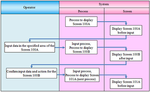
Figure 5: Example of process flow, including operations
Next, we made a state transition diagram. Each screen shown to the operator is set to a specific state in the diagram.
The state is shown using a screen copy with the screen number and the transition symbol, which indicates the transition condition from one state to another. This is shown near the arrow which indicates the direction of the transition, as seen in figure 6.
In the diagram, the state transitions are omitted which are generated in case of the trouble by the operation error. These are represented by statements such as “Close the SpatialAnalyzer (SA) window,” “Run the different measurement plans (MP),” “End the MP,” and so on. These transitions by the operation error could happen in every state, and the transitions go almost always to the same results. Therefore these transitions are omitted to avoid complicating the diagram.
For the same reason, the state transitions are omitted which are generated in case of problems with the software and/or the input and output hardware.

Figure 6: Example of state transition diagram
The transition conditions are summarized in the table seen in figures 7 and 8. This represents every transition symbol which indicates the state transition. By this transition condition table, we could confirm that all the transition conditions should be tested when considering the test procedures.
|
Transition Symbol |
Transition condition |
Test number |
|
100S1 |
Click “OK” button |
1 |
|
100S2 |
Click “Cancel” button |
2 |
|
100S2 |
Click “Close” button |
3 |
|
… |
|
|
Figure 7: Example of transition condition table
|
Test Number |
Step Name |
Screen Number |
Operation procedure |
Items to be confirmed |
|
1 |
Input Information 1 |
100 |
Input “00010” in screen 100 |
Screen 101 is shown. |
|
2 |
Input Information 1 |
100 |
(Show screen 100 again) |
MP ends and it returns to SA screen. |
|
3 |
Input Information 1 |
100 |
(Show screen 100 again) |
MP ends and it returns to SA screen. |
|
|
... |
|
|
|
Figure 8: Example of test items in test procedures
Conclusion
In the development of semi-automatic measurement system, the time for adjust specifications and confirmation was reduced drastically by streamlining the design method. The quality of the measurement system was also improved by taking the reliable test method.
By separating the specifications directly related to the operation and the processing which is the manufacturer’s responsibility, the time to adjust specifications was reduced. The operations were easy to understand and it was easy to request changes for the operator. Specification changes had not occurred, because there was no misunderstanding between the system users and the system developers.
During the test run, the user requested to add the confirmation process after the measurement by the operator. We could add the confirmation process within a short time because the portion to be changed was localized.
We think that this system design method is useful for 3D measurement system from a viewpoint of offering the modifications easily corresponding to the diversification of future types of products.
Moreover, the fully automatic measurement system would include an unspecified problem. When this problem happens (which could not be carried out by automatic processing), the operator could not respond to that problem because the relationship between the human and a system becomes tenuous. We think that the semi-automatic measurement system, which is made to intervene intentionally and effectively, becomes important as the solution to that problem. Otherwise, the development method of the system would become increasingly complicated.
We intend to continue developing these technologies to expand the applicable fields of the 3D measurement by applying the methods obtained during development of this 3D measurement system. We will store and analyze the measured data of this measurement system and try to improve the production processes by optimizing the measurement and investigating the most efficient possible operations.
Acknowledgements
We would like to express our appreciation to Nikon Metrology for developing the measurement system using the LR, and to New River Kinematics, as we used SA to automate the measurement processes.
Add new comment