by Johan Gout
When it comes to the problem of cramming 10 lb of stuff into a 5-lb box, nobody understands the issues better than Robert Montgomery, inventor and CEO of Power-
Ski International Corp. His product, a motorized surfboard called the PowerSki Jetboard, looks a lot like a traditional surfboard, except that the 200-lb watercraft can hit speeds approaching 40 mph with a 185-lb rider standing on its deck. Inside its sleek fiberglass body is a custom-designed jet-ski motor, exhaust system, fuel tank, battery, control mechanism and not a square inch of wasted space. How PowerSki got all that to fit inside a 10-in-thick hull illustrates the possibilities afforded to manufacturers who use high-density 3-D scanning equipment and digital assembly techniques. This article will explore digital assembly and how PowerSki fit a whole lot of fun into an itty-bitty space.
Faster acquisition rates, more thorough part capture, and the portability of 3-D scanning devices such as laser scanners and structured light scanners have made these devices invaluable in many industries. Companies such as Boeing, Mattel, Pratt & Whitney, SeaRay, Sony Entertainment, and Toyota all use 3-D scanning to support their inspection and reverse-engineering processes.
Inspection and reverse engineering are only part of what you can do with scanned data. Some 3-D scanning solutions can generate a little-known, and very useful, deliverable referred to as a "digital assembly." You may already create digital mockups (DMU) or digital assemblies using a computer-aided design (CAD) system on a daily basis. The key difference is that the 3-D scan data used in a digital assembly reflect the "as manufactured" or "as assembled" condition of that specific assembly. The "as manufactured" part differs from CAD nominal due to manufacturing tolerances, whereas the "as assembled" configuration differs from the CAD DMU due to part manufacturing variances, assembly stack-up, positional tolerances and so forth.
To generate an accurate "as assembled" digital assembly, two main criteria must be met. The first is the ability to acquire the actual positional orientation of each component in the "as assembled" configuration. The second is to generate the "as manufactured" scan representation of each component in the assembly. Depending on the assembly's overall size and complexity, this can be accomplished in two ways. In these examples, the measuring device is the ATOS structured white-light scanner from Capture 3D Inc.
Scenario 1
This scenario utilizes capabilities within the scanning system to provide a global common reference for all components in the assembly. A simple and effective example of this process is conveyed with a desktop phone. In this scenario, the scanning system will be used to capture the 3-D "as manufactured" representation of the handset and base unit, and it will also generate a global reference coordinate position file that provides the location and positional orientation of each component. (See image below.)
A 3-D scan of telephone handset (top) is combined with a scan
of the base unit to produce an "as assembled" model. To do this, adhesive or magnetic circular markers--i.e. targets--are applied to the assembled components. These targets, when identified by the software, serve two purposes. They provide location and positional coordinates as to how the handset and the base unit fit together, as well as support the automatic scan-to-scan patch alignment during the scanning process (i.e., adjacent area scans are accurately stitched together in software). The dual-camera scanner has a "find reference points" function that quickly and automatically identifies these markers via an automated ellipse-finding algorithm. The result is a global reference file that contains the x , y and z coordinate values for the center point of each marker, a unique identification number for each marker, and the relationship of all markers to one another.
|
The digital assembly process is often utilized in engineering and quality departments to validate, troubleshoot or perform root cause analysis on their products. Beneficial information derived from an “as assembled” digital assembly includes:
• The following component and assembly data for interrogation:
— Dimensional analysis
— Deformation analysis
— Positional analysis
— Component-to-component analysis, i.e., contact, clearance and interference information
• Assembly and component data for finite element analysis (FEA) and computational fluid dynamics analysis
• The ability to capture component orientation based on a common global reference system, such as automotive or aircraft coordinate positioning. The physical components can be removed from the assembly and fully scanned, and the digital definition automatically placed back in the “as assembled” location.
• The ability to utilize aircraft, automotive, or user-specified coordinate positions, in which the “as built” assembly can be compared to the CAD assembly, producing a full-color deviation report
• The ability to interrogate dimensionally the areas that are inaccessible once a product is assembled
• Assembly form, fit and function analysis including travel path of moving parts
• Competitive benchmarking analysis
|
Once the "as assembled" reference file has been obtained, the scanning begins. The handset is taken off the base unit and completely scanned independent from the base unit. Each scan is automatically transformed into its correct location based on automatic identification of the targets seen in that scan. The same scanning process is performed on the base unit. The result is two separate scan models that have a common coordinate position, so if they're opened in the software or in CAD, finite element analysis (FEA) or manufacturing package, they will appear in the "as assembled" position.
This "as assembled" digital definition can then be interrogated for form, fit and function purposes.
Scenario 2
This approach is typically utilized for larger or more complex assemblies, such as vehicle interiors and exteriors, tooling assemblies and full-scale aircraft. A combination of two complementary noncontact data acquisition solutions works to provide an accurate digital assembly deliverable. Digital photogrammetry is performed to generate the global common reference information that defines each component's location and orientation. Then, structured white-light scanning is utilized to quickly and thoroughly capture each component's "as manufactured" condition.
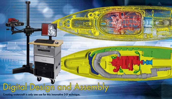
Back to Montgomery and his eye-popping motorized surfboard. Here, digital assembly was used on the Igniter 330 model of PowerSki Jetboard to aid in optimizing design performance, form, fit and function analysis, and to support the creation of higher-volume tooling to lower the jetboard's overall cost of goods, and facilitate transition into high-volume production to meet PowerSki's growing customer demand.
The patented high-performance motorized surfboard and engine are unique. Sitting in the water, the PowerSki Jetboard looks much like a standard surfboard, with the exception of the flexible control cable that comes out of the deck. However, this 100 × 25 × 10 in. surfboard is packed with a 330 cubic cc, 45 horsepower, die-cast engine with enough kick to propel the average speed junkie along the water at 39 mph.
As with any true performance surfboard, its speed and maneuverability are highly dependent on its shape and center of gravity. "We're talking about the hydrodynamics of a craft that has complex curves, and how to capture that," says Montgomery. The guts of the board must be configured to the shape of the board. To get the proper balance of hydrodynamics and component clearance, the prototype was handcrafted and then scanned. The detailed 3-D scans of the board were brought into Pro/Engineer Wildfire for solid modeling in preparation for toolmaking. The scanned board and its components were also digitally assembled in ATOS software to quantify fit, clearances and other issues.
The first step in creating a digital assembly for the jetboard was to capture its components in location and create a common jetboard coordinate reference system.
Uniquely coded targets were temporarily placed on and around the assembly. A high-resolution camera was used to snap multiple images at various angles and locations around the assembly, with each image capturing some of the targets. The Wi-Fi camera connection immediately transmits the images to the photogrammetry software, at which point the mathematical bundling of the images begins. Based upon these images, the software automatically calculates the 3-D coordinates of the uniquely coded markers as well as the temporarily adhered circular markers. The result is a reference file containing the 3-D coordinates of these discrete markers. Accurate project scale is incorporated via a pair of automatically-identified NIST-traceable scale bars, with known distances between coded markers, which are placed in the field of view during the photogrammetry session. The resultant reference file provides overall dimensional data as well as global and individual component coordinate system information for each component of the assembly. This file is also used for the automatic scan patch placement and scan-to-scan alignment.
After the initial photogrammetry session, the engine and battery covers were removed and a secondary photogrammetry session was performed to identify the target markers on the now-visible components, such as the engine, exhaust, fuel tanks and battery. These sessions supported the generation of location and positional orientation of those components.
The scanning process was performed with a dual-camera structured-white-light sensor. The system is calibrated to capture the component's smallest features, utilizing a NIST-traceable calibration artifact. The ATOS sensor operates by projecting a series of fringe patterns onto the object. These patterns are shifted and recorded by the dual cameras, forming a phase-shift based on sinusoidal intensity distributions on the camera's charge-coupled device sensors. The sensor uses multiple phase shifts in a heterodyne principle to achieve high subpixel accuracy. Precise 3-D coordinates are automatically calculated for each camera pixel based on optical triangulation algorithms. Depending on the sensor configuration, up to four million surface-point measurements can be acquired in seconds. The software has the ability to intelligently sample down the final point cloud or STL file to accommodate downstream processes.
From the photogrammetry session, each PowerSki Jetboard component already had its own location coordinates via the identified markers on the part. Because these are in the same reference as the overall assembly global coordinate position, the components could be removed, completely scanned and automatically placed in the digital assembly. In addition to capturing the object's surface topology, the software invokes an automatic ellipse-finding routine that identifies the target marker centers for those targets seen on that component. Each scan is then automatically transformed into a component location based on matching the scanner-identified target markers to the digital photogrammetry reference file loaded in the ATOS software. This process takes place automatically and gives feedback on the accuracy of the fit of the individual scan in the overall assembly reference, as long as three reference targets are captured in a view. If necessary, scans can be manually merged based on features common between scan patches.
A valuable benefit of a digital assembly is the ability to extract dimensional data in those areas not accessible after the components are assembled. Cutting or sectional planes can be placed at will and dimensions extracted. If there is a CAD assembly model, the software can perform an "as built" assembly comparison and generate cross-sectional "hair plots" displaying the dimensional differences as shown in the images on page 29.
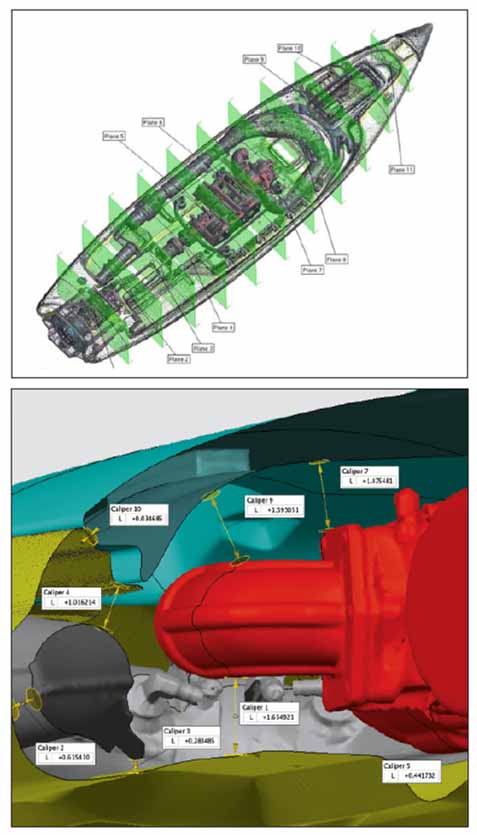
With digital assembly it is possible to look at cross sections of an assembly (top)
and then examine clearances on the "as assembled" model.
Because safety and floatation capabilities of the surfboard are paramount, being able to digitally examine cross sections of the "as assembled" surfboard not only enabled Montgomery and his team to identify possible clearance issues, but also to maximize the amount of foam used in the board's construction so that it exceeds the floatation requirements of the U.S. Coast Guard.
"This is such a valuable tool for us," explains Montgomery. "You have to consider clearances. You have to consider the hydrodynamics of the craft. And you still have to make everything fit. Every quarter-inch is needed. The performance is based on everything being as small and light as possible."
3-D scan data have long been used in inspection and reverse engineering, but much more can be accomplished with the data using digital assembly. The ability to scan components and then digitally assembly a product based on those data allows developers to view or troubleshoot designs in ways not possible with a traditional CAD model. Utilizing a structured-white-light scanner and software, PowerSki designers were able to cram a powerful engine into a safe, sleek, speedy surfboard. Cowabunga!
Johan Gout is director of operations at Capture 3D Inc. (www.capture3d.com). He specializes in helping organizations to integrate 3-D measuring solutions. Capture 3D's ATOS and TRITOP solutions (www.gom.com ) greatly reduce the time and costs associated with first article inspection, quality control, root cause analysis, CFD/FEA modeling and reverse engineering by providing a robust, intuitive and effective deliverable in a timely manner for parts ranging from turbine blades to full-scale aircraft.
Gout holds a bachelor's degree in mechanical engineering from Cal State Long Beach and has more than 25 years of experience in the CAD/CAM/CAE arena with companies such as Hewlett-Packard, Parametric Technology and Imageware.
Capture 3D will be exhibiting at the CMSC in Reno, Nevada, July 16-20, in booths 405 and 505.
|