| by George Schuetz
When digital electronics were introduced 30 years ago, many predicted the end of all analog devices, from dial indicators to watches and speedometers. It hasn’t happened. Analog watches have returned to popularity, speedometers remain largely analog, and for many gaging applications--where degrees of motion or degrees of good or bad must be detected instantly--nothing can replace the human eye in interpreting the movement of a sweeping indicator hand.
 Nevertheless, today’s digital devices are doing more, for less, and providing features even their early proponents couldn’t have predicted. Not only have these devices replaced analog dial indicators in many applications, but they’ve also evolved to closely resemble bench amplifiers in features and flexibility of use. Nevertheless, today’s digital devices are doing more, for less, and providing features even their early proponents couldn’t have predicted. Not only have these devices replaced analog dial indicators in many applications, but they’ve also evolved to closely resemble bench amplifiers in features and flexibility of use.
Because they’re mechanical, dial indicators are pretty much fixed for their intended use. When specifying a dial indicator, you must know the measuring range, direction of movement and whether the dial will read out in inches or millimeters. These basic characteristics are built into the indicator, and once you buy it, that’s all it can do. Switch to a new application with a different measuring range or resolution, or try to measure an inside diameter instead of an outside diameter, and you’ll probably have to buy a new indicator.
Early digital indicators suffered some of these same limitations, but today’s generation can do it all--switch from inches to millimeters, change polarity and/or select resolutions. A host of models and choices are available to meet any gaging requirement. In fact, there are so many options, and such a range of prices, that selecting the right product can be confusing.
In this article, we’ll look at the functionality and some major features of digital indicators to help you target the right gage for your application and save money in the process. But first, let’s look at some applications where analog indicators haven’t yet succumbed to the digital revolution.
When a measurement only needs to fall within a certain tolerance range, analog dials are often quicker and easier to read than digital displays. An experienced gage operator simply checks to see whether the pointer is within tolerance, rather than taking the time to read and interpret the numbers on the dial.
For example, experi-enced quality control inspectors can make consistently accurate go/no-go readings with dial indicators even before the pointer has stopped moving. They can tell at a glance approximately where the pointer will stop, and in many applications, that’s close enough. Electronic indicators don’t give you the option of approximating. When a digital device is flickering between six and seven, all the elements in an LCD display may be lit, appearing as an eight.
Skilled operators can also “split grads” with dial indicators, i.e., resolve the pointer’s position to about one-fifth the gage’s stated minimum graduation value. Further, analog dials enable a machinist to observe the direction a process is headed. If the first reading measures one-fifth of a grad greater than zero, the second reading is precisely zero and the third reading is one-fifth of a grad less than zero, the user is able to draw valuable conclusions about the condition of his or her tool. In other words, dials can provide more information than simply the dimensional measurement. A digital readout would, however, read zero in all three cases, depriving the user of this additional information.
Digital indicators’ clearest advantage is for data collection in process control. Digital devices can output measurements directly to printers or statistical process control programs with no operator errors in reading or recording. The operator has only to position the workpiece and press a button or foot pedal; reading the measurement isn’t necessary. With dial indicators, the operator must interpret the pointer’s position to read the measurement, then record it, usually by hand. Finally, the data must be keyed into a computer. That makes three steps during which errors can--and frequently do--occur.
A related problem, common among users of dial indicators, is failing to notice whether the pointer has made one or more full revolutions. Parts that are grossly out of tolerance might appear to be within tolerance to an inattentive operator. In contrast, digital indicators never come “back to zero,” eliminating this problem entirely. Furthermore, all digital indicators can be made to signal out-of-tolerance dimensions.
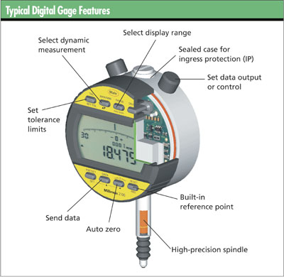
The latest digital indicators can take and hold certain types of readings even while the workpiece is being manipulated. These dynamic measurement capabilities include “min,” “max” and “TIR” (total indicated reading) and give digital gages many of the functions usually found in electronic amplifiers, which include bench amplifiers, column gages and digital amplifiers.
The min and max features enable an operator to capture the gage’s smallest or largest measurement of a dimension without having to watch as the readout flickers up or down. This eliminates one of the liabilities of earlier digital indicators: the impossibility of taking a reading, even an approximate one, until the workpiece and the gage were both absolutely stationary.
Rocking-type bore gages are a popular application for the min feature. The operator inserts the gage into the bore, pushes a button to select the min function and rocks the gage. The indicator remembers the measurement and displays only the smallest dimension detected--i.e., the true diameter. It ignores any larger dimensions, such as those indicated when the gage isn’t perpendicular to the bore.
The max feature can be equally useful. For example, when measuring outside diameters on a bench comparator, the operator rolls a part under the contact and the indicator reads the largest dimension detected. The operator needn’t even look at the readout while handling the workpiece because the reading remains on the display until the indicator is reset.
Min and max features are even more effective when used in conjunction with data collection systems. If a tolerance is unilateral--i.e., only the maximum or the minimum reading is critical--then the operator can transfer the reading even under dynamic conditions. It’s no longer necessary to hold the gage steady while simultaneously attempting to press the “send output” button.
The TIR feature is used most often in measuring the runout of shafts, so it’s sometimes called “total indicated runout.” But TIR can also be used to check thickness variation in flat parts and other differential applications. For example, a shaft is put on a gage and rotated through 360 degrees or more. The indicator notes both the min and the max readings but displays neither one. Rather, it remembers both readings, then calculates and displays the spread between them. (For example, if the min is -0.001 in. and the max is +0.003 in., then the TIR is 0.004 in.) The reading doesn’t change, even if the operator continues to rotate the shaft, because min and max remain the same.
Another related feature is “hold/reset.” This is used primarily where the readout is difficult to observe: for example, where the entire gage is inserted into a part to measure an awkwardly placed internal dimension. The hold feature allows the indicator to retain the reading so that the operator can extract the gage and view the readout, then clear it with the reset button.
There are two types of digital indicators. The difference between the two depends on their measuring range and the transducer technology used.
Digital comparators are short-range, comparative-based indicators based on various types of coil and core transducers, similar to linear variable displacement transducers (LVDT). These offer ranges very similar to those seen in a standard American Gage Design dial indicator.
The measuring range of digital indicators, on the other hand, is most commonly 12 mm/0.5 in. or 25 mm/1 in., although 50 mm/2 in. and 100 mm/4 in. versions are also available. These longer-range indicators are based on a scale technology in which the accuracy is built into the transducer.
Because early digital indicators were designed to be dial-indicator replacements, they tended to have dial-indicator performance characteristics. The repeatability and accuracy of dial indicators is specified in grads or parts of a grad, with most indicators having grads of 0.001 in. or 0.0001 in. With today’s tighter tolerances, however, a digital indicator having dial-indicator accuracies would not be accepted. Today, users want the performance of digital indicators (i.e., those indicators that can fit into the palm of your hand) to approach that of a LVDT and full-featured, bench-mounted digital amplifier.
A digital comparator is very close to being a bench-mounted digital amplifier shrunk down to the size of a digital indicator, and costing thousands less. The highest performance digital comparators can have resolutions to 0.0002 mm/0.00001 in.
and accuracies of 0.0003 mm/0.000012 in. over their measuring range.
Digital comparators are ideal for replacing dial indicators on existing or new bench or hand-held gages. Most mechanical gages have very limited actual measuring ranges, usually less than 1 mm/0.04 in. The advantage digital comparators offer is their size envelope. Because they do not need the large dust caps of some of the longer-range digital indicators, they are more suitable for
portable gages. Also, for some high-accuracy requirements, the
high-performance digital comparator replaces the LVDT and bench-mounted digital amplifier. This reduces cost and actually puts the digital display right in front of the operator, making it easier to read.
Digital indicators provide much better performance than long-range dial indicators. The technology provides a means of correcting for small repeatable errors found in the indicator’s transducer. Over the years the accuracy of digital indicators has improved dramatically. Newer indicators have resolutions of 0.001 mm/0.00005 in. and accuracies of 0.005 mm/0.0002 in. over their full measuring range of 50 mm/2 in.
Long-range dial indicators that can be used for direct measurement applications have existed for decades. These were some-times referred to as drop gages, where the long-range indicator was mounted in a bench stand and used for general-pur pose part measurement. Although they’re familiar and reliable, long-range dial indicators aren’t easy to read. Workers often make errors when trying to interpret the rather complicated display, which, in addition to the main dial, includes one or two revolution counters rotating in opposite directions.
Because the display of a long-range digital indicator shows the actual transducer position, it eliminates the readability problem of dial indicators. Simply zero the indicator on the reference, and the digital display presents the actual part size as the transducer is moved to various locations on the part. Long-range digital indicators typically have measurement ranges of up to 100 mm/4 in. and resolutions of 0.001 mm/0.00004 in. Invariably they’re equipped with lifting levers so that the contact point can be easily raised and lowered.
Today’s feature-packed indicators al-so allow users to choose the best resolution for their gaging requirements. One common application error is caused by having too many digits visible on the display. Flickering digits make the gage look unstable and can confuse the operator. Keep in mind that more digits don’t mean better measurements. Turning off the extra digit stops the flicker and simplifies reading. Matching resolution to the gage performance just makes the user’s job easier.
A number of features included in newer gages are designed to take guesswork away from the operator. These include:
 Preset features. These place the actual part size on the display so the operator can match the print to the indicator. Preset features. These place the actual part size on the display so the operator can match the print to the indicator.
Tolerances. By allowing the display
to classify the part, operator influence can be reduced. Tolerance can be set as balanced or unilateral (i.e., on both sides or one side). Thus, with an indicating symbol, the operator can easily see whether the part is good or bad. Many digital indicators also incorporate colored displays--i.e., green when the part is good, red when it’s out of spec.
It’s important to lock out these changeable features. Nothing is worse than nimble fingers sneaking in and changing these flexible features in process. Through passwords, special programming keys or remote setup by computer, these features can be locked out. This makes the digital indicator almost like an analog one: purpose-built or set up for an application, although in this case, the electronics can be changed later. The operator sees what he or she needs to but isn’t tempted to make changes.
Finally, some indicators come with multiplication factors. Often used with three-point gaging, levers and such, these indicators have selectable multiplication factors built in for these applications.
Two technology changes have significantly affected the performance of digital indicators. Because digital products were meant to replace dial indicators in portable applications, they couldn’t have their portability limited by power cords. They needed a battery to work. Recent advances in battery technology have coincided with circuit designs that consume less power. These two factors have extended battery life in products to two or more years of typical use.
However, for bench gages portability isn’t an option. In these cases, the power cord is not an inconvenience but a benefit in that it allows for power-hungry features such as lighted, color-changing displays. It also eliminates downtime for battery changes.
Digital electronic gages have become increasingly common on the shop floor because of their ease of use, speed and ability to take complex measurements. However, when it came to caring for early digital gages, you didn’t want to get one anywhere near water or coolant, or there was sure to be trouble. Either the gage wouldn’t work, or--even worse--it would produce incorrect readings.
Major improvements to many electronic gages have finally given these tools the characteristics needed to survive on the shop floor. Advances in scale technology, microcircuits and sealing even allow gages to make measurements under water.
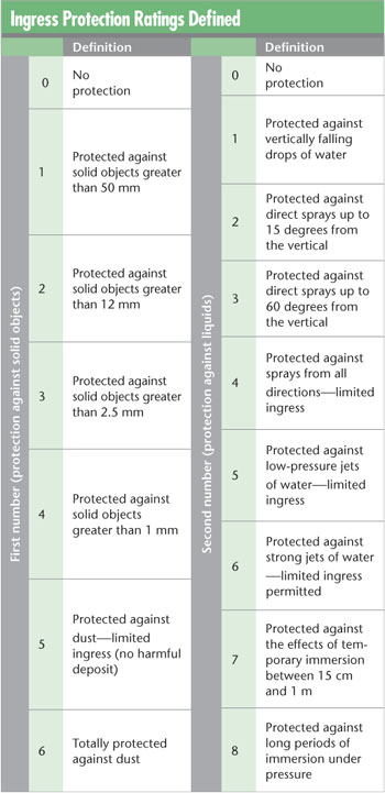
A new standard has been set up to help identify what type of tool is best for the environment in which it will be used. This rating is called ingress protection (IP). Associated with the IP is a two-digit rating number that tells what type of conditions the gage can survive in. The first digit describes the protection factor for solid foreign objects, while the second digit indicates protection against harmful ingress of water. A third digit, which is the defined impact protection, hasn’t yet made its way into the measuring instrument table, which is detailed in the figure on the following page.
For example, a gage with a rating of IP-65 is totally protected against dust and low-pressure jets of water from all directions, with limited ingress permitted. Today there are calipers and micrometers with ratings as high as IP-67. These can be subjected to the type of dust and dirt found in the shop and are both water- and coolant-proof.
However, just because a gage can handle the environment doesn’t mean the measurements taken with it are impervious to environmental conditions. These are still precision gages, and all the basic rules for precision gaging still apply.
To summarize, although it’s clear analog indicators will be around for a long time, digital indicators will continue to improve. In the crystal ball are advances such as better specification performance, longer battery life, wireless data transmission, better graphic displays, displays tailored to applications, more measurement programs, and more intelligent indicators that combine statistics and make decisions (and even recommendations) about the measurement process.
A well-known writer and authority on dimensional gaging topics, George Schuetz is director of precision gages for Mahr Federal Inc. and the current president of the American Measuring Tool Manufacturer’s Association. He can be reached at george.schuetz@mahr.com.
|
 Ingress protection ratings