| by Dick Mierzejewski
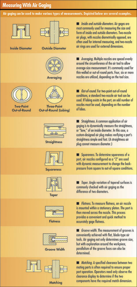
Glossary of Air Gaging Terms
Amplifier--the readout
of an air gage system. An amplifier is a device containing
the necessary restrictions to change the pneumatic
pressure or flow. It displays readings on a scale
as dimensional values. When connected to air gage
tooling, readings are amplified many times, allowing
the user to easily read the size being measured.
Balance--the resultant
nonmovement on the display of an air amplifier that
occurs when one nozzle of a two-nozzle tool is closed
toward the workpiece and the other nozzle equally
compensates for that movement
Column--an air-electronic
amplifier or a flow system amplifier featuring a vertical
bar graph display or flowmeter tube
CTS--air tooling designed
to measure close-to-shoulder, such as an air plug
used to measure counterbores. Removal of front-center
post on air plugs below 2.510 in. becomes a blind-hole
design.
Flowmeter tube--a graduated
glass tube of a precise size with a “floating”
cork that displays the readings on a flow air gage
system. Different size tubes are necessary to accommodate
all air gaging applications.
Full scale value--the
numeric equivalent of the graduated display. FSV is
usually 1.5 to 2 times greater than the tolerance
being measured to show approach or oversize conditions.
Magnification--the visual
increase of size that is created by an air amplifier.
In systems in which the air amplifier has adjustable
magnification, this is accomplished by adjusting the
flow or back-pressure within the amplifier to agree
with the master sizes. On systems that have an air
amplifier with fixed magnification, it’s essential
that the air gage tooling is precise for full amplification
to be achieved.
Nozzle--the orifice in
the air gage tooling that emits the air that blows
against the part being measured. The diameter size
of the nozzle is dictated by the air gage system used.
The quantity and location of nozzles are determined
by the measurement application.
Nozzle drop--the engineered
distance that a nozzle is recessed below the surface
of the air gage tool. Nozzle drop is governed by the
air gage system. A deeper nozzle drop can provide
longer wear life of the air gage tool.
Resolution--the smallest
increment on the full-scale display of the amplifier
Restriction--a device
used to control air pressure or flow within an air
gage amplifier. This may be done with a fixed orifice
of a precise size, with adjustable needle valves or
with both.
Zero--the process of
positioning the magnified spread on an amplifier to
a desired relative position on the scale. Zero is
generally at midpoint of the full scale, but the spread
may be positioned anywhere.
Zero size--the desired
midpoint or nominal size of the feature being measured
as it relates to the scale. On back-pressure systems,
zero is usually the midpoint between the minimum and
maximum allowable size. On the flow system, zero is
generally the minimum size.
|
In the competitive world of
manufacturing, many companies are looking to increase quality
and productivity while reducing frivolous expenses. Some
have set their sights on noncontact measurement as a means
of saving valuable resources. One such type of measurement
is air gaging, a method of precise comparative dimensional
measurement that offers users the advantages of improved
workflow, increased productivity and decreased downtime.
As this article explains, air gaging is ideal for measuring
dimensions with tolerances smaller than 0.005 in. When gaging
tight tolerances, resolutions as small as 0.000002 in. can
be achieved. Its noncontact characteristic makes air gaging
particularly useful for checking soft, highly polished,
thin-walled or other delicate materials.
Chief among the benefits of air gaging is its ease-of-use,
which helps produce accurate results even when performed
by unskilled employees. Operation is as simple as presenting
a tool to a workpiece and observing the reading. Speed is
another benefit: A row of multiple-column amplifiers can
be scanned in one glance, reducing time and fatigue. Moreover,
relationships (e.g., squareness) that cannot be checked
by fixed-limit gaging--and are costly to do by other means--are
easily measured with air gaging.
Air gaging is also economical. Once the basic system is
purchased, relatively inexpensive additional tooling can
be used for a wide variety of applications. Air gages effectively
measure all common types of dimensions and are particularly
suited for measuring dimensional relationships and match
gaging.
Most air gaging systems operate at air pressures that
can purge workpieces of contaminants (e.g., abrasive particles,
coolant, etc.) at the measurement point, eliminating the
need for separate cleaning in most operations. And, because
air gage tooling has no moving parts, it’s virtually
immune to fouling. Air gaging offers a wide choice of tooling
for single or multiple measurement applications, and when
repair is needed, air tools are simple to fix.
A brief examination of the fundamentals of air gaging
will illustrate the basic premise of air gaging and its
evolution into today’s manufacturing environment.
To achieve its precise dimensional measurement, air gaging
relies on a law of physics that states flow and pressure
are directly proportionate to clearance and react inversely
to each other.
The regulated air flows through the restriction (e.g.,
a needle valve or jeweled orifice) and then through the
nozzle. When the nozzle is open to the atmosphere, there
is maximum flow through it with minimal pressure--called
“back pressure”--between the restriction and
the nozzle.
As an obstruction is brought closer to the front of the
nozzle, air flow from the nozzle diminishes, and back-pressure
builds. When the nozzle is completely obstructed, air flow
is zero and back-pressure reaches the pressure of the regulated
air supply. During this example, air flow moves from maximum
to minimum, whereas back-pressure moves in the opposite
direction: minimum to maximum.
These values can each be plotted against the nozzle’s
clearance from the obstruction. Except for the extremes
of both back-pressure and flow, the curves are straight
lines, representing the linear proportions that establish
the basis for all air gaging.
Thus, measured decreases in flow provide an accurate correlation
between the distance of the nozzles in the air gage tool
and the obstruction (i.e., the surface of the workpiece
being measured). Similarly, increases in back-pressure indicate
less distance between the tooling nozzles and the workpiece.
Although the concept of air gaging may be new to some,
the technique itself has been around for decades.
Air gaging is a proven technology that has been refined
for more than half a century. The first back-pressure air
gages were developed in France before World War II by a
carburetor manufacturer seeking a method of gaging its carburetor
jets.
The company relied on one of the simplest air regulators
ever developed. The first restriction suitably reduced the
air pressure, and an open-ended tube from a “T”
in the air line was submerged in water. Any air contributing
to pressure in excess of the pressure at the depth of water
bubbled out the bottom of the tube.
The water column also rose in the indicator tube fed from
its bottom, and a second restriction before the “T”
in the air line between the top of the indicator tube and
the air plug provided zeroing control. As back-pressure
affected the level of water in the tube, distance between
the air plug nozzles and the workpiece wall was indicated.
In 1943, a patent was issued for the simple system--the
basis of today’s back-pressure air gages. One of its
important features was the use of the newly developed pressure
regulator, which eliminated the evaporation problem of the
first system. Also noteworthy is its direct indication of
dimensional deviations by means of a dial readout. At about
the same time, another company developed a system for measuring
the flow variation rather than the back-pressure.
Improvements in air gaging systems continue to the present,
adding back-pressure bleed and back-pressure differential
systems to the roster of simple back-pressure and flow technologies.
This article examines all four contemporary systems, as
well as today’s enhancement of measurement precision,
flexibility, speed and usefulness through amplifier technology.
Air-electronic amplification and data collection/processing
have raised the resolution of air gaging to the level of
millionths of an inch while providing output of measurement
data for statistical process control.
Four general types of air gaging systems are in use today:
back-pressure bleed, back-pressure, differential and flow.
Each has definitive characteristics that affect its diversity
of application, accuracy, efficiency and ability to compensate
for degradations of associated tooling.
The “bleed” feature in this configuration
accomplishes the back-pressure bleed system’s greatest
benefit--its versatility. Tooling for different air gaging
systems may be used with the back-pressure bleed.
The back-pressure bleed system is configured with a fixed
regulator to control incoming air pressure for maximum linearity.
Key to this system’s uniqueness is the important addition
of a second adjustable restriction in the feed line opposite
the output leg. This second restriction allows users to
adjust for different air gage tooling, as illustrated below.
Back-Pressure Bleed System
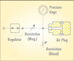
The system’s magnification is controlled by the
typical adjustable restriction between the regulator and
air tool. The second adjustable restriction releases excess
air into the atmosphere to adjust the zero position. Two
setting masters--minimum and maximum--are used to calibrate
the system, defining and displaying both ends of the tolerance
range for accurate reading of workpiece deviation.
Single-master systems indicate only nominal conformance
at the zero point. The back-pressure bleed system defines
the tolerance range and explicitly indicates the location
of any workpiece in that range. No bad part ever passes.
These systems can also compensate for gradual tool wear
or variations in tooling sensitivity and allow the use of
different nozzle sizes without losing full amplification.
Back-pressure bleed systems operate at generally higher
air pressures than other systems, permitting greater nozzle
drop. Nozzles are more protected against wear and damage
that can affect measurement accuracy. The higher air pressure
also offers better self-cleaning properties.
This system is capable of the broadest magnification adjustment.
It accommodates almost any size nozzle, as large as 0.093
in. or as small as 0.020 in. This is especially beneficial
when small nozzles are required to check narrow lands.
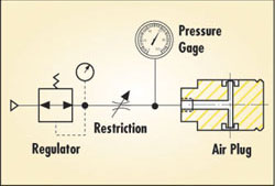
Remove the second adjustable restriction from the back-pressure
bleed system, and you get a back-pressure system. This two-master
system operates just as the back-pressure bleed without
the tooling versatility. The back-pressure system requires
dedicated tooling and amplifiers with limited ranges.
Back-Pressure System
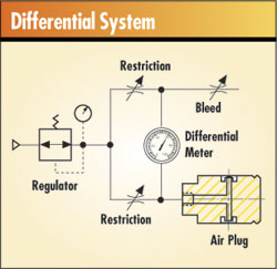
In a differential system, sometimes referred to as a “balanced”
system, the air stream is divided and flows through two
fixed restrictions, as illustrated below. One side of the
system, the bleed leg, ends in a zero valve that balances
pressure to the fixed second leg of the system, terminating
at the air plug. The difference between these two legs is
measured by means of the differential pressure meter, which
bridges the two legs.
The differential system is set to zero using a single
master for each tooling configuration, making setup somewhat
faster. However, the differential system amplifier can only
be set to zero. Damaged or worn tooling could result in
inaccurate readings. Additionally, with a single-master
system, the entire amplifier must be calibrated--rather
than just the masters, as in two-master systems.
Tooling for the back-pressure differential system must
be ordered for each magnification. Because the single-master
system has fixed magnification, worn, damaged or fouled
tooling must be returned to the manufacturer for service.
Another drawback of this system is that each amplifier only
accommodates one full-scale value. If an application requires
the measurement of different tolerances, several amplifiers
may be necessary.
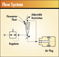
The air flow method is measured and read in a flowmeter
tube that supports a float. It’s a two-master system
with magnification and zero position set by two adjustable
restrictions, as illustrated on page 35. As such, the flow
system provides accuracy in reporting workpiece deviations
within tolerance, similar to the back-pressure bleed system.
The range of magnification is augmented by changing flow
tubes and scales rather than by a simple adjustment.
Flow gages, by their nature, require a greater volume
of air to generate movement of the float. This requires
tooling with larger nozzles, which must be kept closer to
the part by designing them with a shallower nozzle drop.
Shallow nozzle drops can shorten tool life. Also, when measuring
smaller workpieces necessitates smaller air plugs and smaller
nozzles, it’s difficult to get full amplification.
To its credit, the flow system can be used with long hoses
without affecting the response time of the amplifier. This
feature makes the flow system ideal for checking long holes,
such as gun barrels or oil drill bushings.
The variety of air gaging methods offer users both the
benefits of noncontact measurement and a number of choices
depending on the specific applications. Each option’s
ease-of-use will come in handy during high-yield production
schedules, and their accuracy won’t compromise your
organization’s quality efforts. When seeking a noncontact
means of metrology, air gaging could be the answer to your
quality measurement questions.
Dick Mierzejewski is manager of sales engineering
at Edmunds Gages. He has more than 30 years of engineering
experience in the field of metrology, specializing in air
and electronic gaging, automation and custom vision systems.
He can be contacted at rmierz@edmundsgages.com.
|