Noncontact Measurement for
Today and Tomorrow A new generation of Coherent Laser Radar
promises to revolutionize noncontact measurement.
by David A. White and Jack Shry Industries have come to expect precision measurement almost to the point of
taking it for granted. Even as technology evolves toward lasers and away from traditional contact CMMs, which still represent the standard, precision
measurement continues to include some element of contact. Even laser trackers are contact measurement systems. Most existing noncontact systems require
sensors that measure only in close proximity to the surface of interest. It's only recently that technology has made large-scale, noncontact precision measurement
possible with the advent of a new type of laser radar: Frequency-Modulated Coherent Laser Radar (FMCLR). The new generation of FMCLR instruments precisely measures large-scale
geometry without requiring photogrammetry dots, laser tracker spherically mounted retroflectors, retroreflectors or probes. Although the technology has
been used by U.S. government agencies since 1993, it's only recently become available in a commercial system that can be integrated more easily into remote automated manufacturing systems.
Who needs this noncontact benefit?
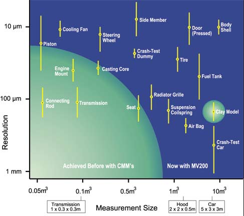
The aerospace and automotive industries have typically taken the lead in finding innovative solutions to measurement problems. Figure 1 highlights some of the
automotive components whose production utilizes noncontact applications. Auto industry leaders have incorporated FMCLR noncontact measurement technology
into their design centers for model digitization and reverse engineering. Aerospace firms such as Boeing are also early adopters of the coherent laser radar system,
and even antenna manufacturers have improved the performance of their antennas by identifying, modifying and rechecking subtle surface irregularities. Figure 1: Noncontact Sphere of Opportunity (Automotive)
Noncontact measurement speeds manufacturing, improves quality and lowers
manufacturing costs. An FMCLR instrument can be used to accurately align large parts during assembly. It can certify tooling and then monitor repeatability during
production. It can be used to scan objects that were previously impossible to scan due to their size, inaccessability, very complex geometry or delicate
surfaces. It operates at the object's location without a conditioned environment and without the need for expensive tooling. Offset calculations aren't required
because measurements are taken directly from the part surface. The system, whether used indoors or outside, can operate in any lighting and on any surface with a reflectivity of 1 percent or more.
FMCLR can be used for many applications. It can rapidly sample metal, plastic and composite as-built surfaces and compare them directly to a CAD model. It
can gather data over extremely large areas in a contiguous coordinate system and, because operators can accurately measure from key features or reference
points as they go, relocating the system eliminates the need for complicated reassembly of data clouds. For those who want to digitize models or hand
lay-ups, data can be gathered in uniform scans with control of point density and area and then be exported directly to a wide variety of CAD packages.
Tool builders can locate and adjust tool positions and features in real time, driving the system to a specific point in space and measuring a part continuously
until it is positioned at its nominal location. Operators can also measure tools and surfaces for wear, monitoring surfaces for tolerance and stability and documenting
tools and die surfaces. For in-process applications, the system can support robotic positioning and then monitor conditions like orientation, gap, flushness
and fit. In addition, it can be used to monitor tool and fixture stability during use without the need to manually collect datum information. A single machine can
monitor several manufacturing work cells automatically without the need for operator intervention.
For quality professionals, an FMCLR can perform first-article inspections and be used for incoming, in-process and outgoing quality assurance. Because the
instrument can scan a part surface directly, it's well-suited for measuring tight pockets, small holes and otherwise inaccessible areas. For routine maintenance,
the system can perform static and dynamic inspections of aircraft, automotive and heavy equipment tooling assemblies. It can monitor deformation of building,
tunnel and bridge structures and accurately measure surface fractures that can provide early warning to possible fatigue and structural failure--an especially
useful capability after seismic activity. Inside the system
The newest commercial instrument utilizing FMCLR is MetricVision's MV200, which takes a fresh approach to industrial design. It's a versatile instrument with
many applications that integrates all of the technology into the measurement head itself and is powered by a small remote power-supply module. An
impact-resistant molded exterior protects an ultra-precision scanner and optics housing. The interior structure is thermally stable and very rigid. The combined
metal and plastic assembly delivers high performance while reducing weight. The scanner assembly can be mounted to a robot or gantry or fixed in an automated
cell, although it's typically secured atop an instrument stand that provides mobility and visual access to surfaces and features around an object to be measured.
Trailing from the instrument is a pair of heavy-duty cables that carry information and power to and from the separate power-supply module. The remote module
can stand alone to gain access to tight areas but is usually integrated into a cart. The cart options are mobile workstations able to fit through tight aisles to get to
the job as well as roll up into minivans for easy transport. The application computer can be a high-performance Pentium notebook or
workstation with an enhanced video board. The computer accesses the scanner by docking to a remote power-
supply module. The MV200 communicates over 10/100 Base-T Ethernet. Its
open interface enables direct software control for embedded applications. The power-supply module incorporates an internal uninterruptable, 110-volt power
supply that's conditioned and provides temporary power when the instrument is briefly unplugged and moved. An optional transformer is also built into the
power-supply module for use with international voltages ranging from 80 to 240 VAC. The workstation/cart can have one or two monitors. (In a two-display
system, one LCD flat screen displays application software while the other flat screen shows a color video image of the area to be measured. In a one-display
system, the larger single display shows application software with a windowed color video image.) Only one person is required to set up the system, and it can continue to run unattended. Data can be imported into leading third-party software to meet a broad range of inspection, quality assessment, reverse engineering and other special application
needs. Software is available internationally from many leading manufacturers including Silicon Graphics (Alias Wavefront's EvalViewer), New River
Kinematics (Spatial Analyzer), Imageware (Surfacer, Inspect It, Build It, Verdict), Verisurf (all packages), Metris and Paraform. How it works The MetricVision system operates using a sensor to direct a focused invisible
infrared laser beam to a point and coherently processes the reflected light. As the laser light travels to and from the target, it also travels through a reference path of
calibrated optical fiber in an environmentally controlled module. The two paths are combined to determine the absolute range to the point. Huge
laser-modulation bandwidth (100 GHz) makes precise measurement possible in a millisecond. The distance measurement is then combined with the positions of the
two precision encoders to determine a point on a surface in space.
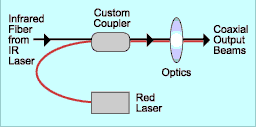
Figure 2: The MV200's Dual-Laser System |
In addition to focusing an invisible spot on a part surface, two visible red-beamed lasers support measurement (see Figure 2). The first is a large-dot pointing laser. It gives an
easy-to-see (but approximate) location of the invisible measuring beam. The second red-beamed laser is precisely coaxial to the measurement beam, which is very
small and gives a very accurate location of the invisible beam's position. The "red dot" emanates from a fiber-pigtailed 660 nm red laser. A custom-made
fiber-optic coupler injects the red-laser light into the fiber that carries the infrared light. Special optical coatings are used on the internal mirror, focusing lenses and
exit window to allow dual wavelength operation. The solution minimizes light loss while risking no loss in sensitivity, and the red dot is as small as the finely focused infrared light. Because of this precision, the red dot feature can be used to accurately identify centers for locating holes. In fact, any CAD feature can be positioned on the part
surface without concern for offsets and cosine errors. Practical applications for the red dot feature include large-scale layout and fabrication. Though it's
especially useful when creating composite parts used in the aerospace industry, it's applicable anywhere.
An example of this feature's usefulness is found in the speed and accuracy of transferring of scribe lines to part surfaces. Currently, the work is accomplished
by producing a Mylar print from 3-D CAD data and positioning the translucent sheet on the shape. A prick punch is used to transfer the shape to the part's
surface. The process can take days or weeks, and it's difficult to precisely locate the two-dimensional Mylar on a three-dimensional part.
In contrast, using a FMCLR system, an operator develops a coordinate system, loads the IGES file and registers the file to the part. The operator can select
discretionary points or drive the scanner to predetermined points. A video camera with zoom permits measurement access to restricted areas with much
improved visibility. In this example, the blank block has tooling balls as fiducials installed to delineate the part frame. The software, Spatial Analyzer, then displays
the CAD scribe line over the part frame. By driving the red dot around the perimeter of the file, the operator is given a fine red target on which to place a
prick punch and leave a fine pattern behind. After points are transferred to the part, the user connects the dots. Additionally, a method of photo etching is in development.
The beam can also be steered to a specific location by means of a remote mouse, and the mouse can then instruct the system to record a point on
command. The intensity of the beam can be adjusted, using the mouse, to compensate for ambient lighting, distance and part reflectance. The finished line
can then be confirmed by pointing the red dot to any portion of the line and comparing the line position to CAD. The total time from import of the data to
completion of a transferred pattern is on the order of minutes. Looking ahead
Major manufacturers of aircraft, large automotive parts and heavy machines are integrating FMCLR technology into their manufacturing processes because they
don't want to wait until parts fail dimensional inspection to take corrective action. By embedding the FMCLR technology into critical processes, they expect to
eliminate scrap and increase production speed in a broad range of manufacturing areas. About the authors David A. White worked for many years for DuPont in Delaware; then, as marketing director of SMX, he contributed to the rapid growth and broad
acceptance of laser trackers worldwide. He has now returned to consulting in Pennsylvania, and he can be reached by telephone at (610) 274-8674 or by e-mail at dwhite@qualitydigest.com . Jack Shry is vice president of sales at MetricVision, about which he and his
team welcome all inquiries. For more information, visit www.metricvision.com or telephone (703) 550-2945. E-mail Shry at jshry@qualitydigest.com . |