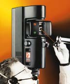
The accuracy and speed of the laser tracker distinguish it
from other portable coordinate measuring instruments. Many industries, including the automotive and aerospace industries, must precisely measure the three-dimensional features of large objects. An increasingly popular way to do this is with the versatile laser tracker, a device first introduced in the late 1980s. As its name suggests, the laser tracker measures coordinates by tracking a laser beam to a retroreflective target held in contact with the object of interest. A laser tracker can measure object features up close and as far away as 35 meters, with an accuracy of 25 microns (0.001 inch) at 5 meters. It collects coordinate data at high speed and requires just one operator. The benefits made possible by laser trackers include not only improved methods of coordinate measurement but also new manufacturing methods. Competing coordinate measuring instruments
(Click for a comparison of competing technologies) Today, many instruments can measure coordinates. Each is best suited for certain applications. Traditional fixed coordinate measuring machines make repeated measurements rapidly and accurately. Although CMMs are immobile, limited in measurement range and expensive for large applications, their speed and accuracy make them popular for inspecting small to medium-sized (i.e., under 1 meter) production components. For medium to large parts, portable CMMs are preferred. Until the advent of laser trackers, portable coordinate measurement was done predominately with theodolites, total stations (theodolites equipped with electronic distance measurement), jointed-arm CMMs and photogrammetry. Each has its inherent drawback. Laser trackers excel by providing high accuracy, high speed and ease of use. How laser trackers work Operationally, a laser tracker is easy to understand: It measures two angles and a distance. The tracker sends a laser beam to a retroreflective target held against the object to be measured. Light reflected off the target retraces its path, re-entering the tracker at the same position it left. Retroreflective targets vary, but the most popular is the spherically mounted retroreflector. As light re-enters the tracker, some of it goes to an interferometer that measures the distance from the tracker to the SMR. Figure 1 shows the path from a helium-neon laser to the retroreflector and back into the interferometer. Also shown are the angular encoders. These devices measure the angular orientation of the tracker's two mechanical axes: the azimuth axis and the elevation axis. Measuring the encoders' angle and the interferometers' distance is sufficient to locate precisely the SMR's center. Tracker software applies an offset equal to the SMR radius to obtain the coordinates of the scanned surface. 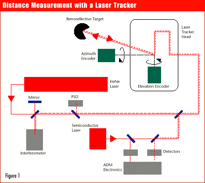
Distance measurement, an important function of the laser tracker, can be either incremental or absolute. An incremental distance measurement is made with an interferometer and a frequency-stabilized, helium-neon laser. The laser light splits into two beams. One travels directly into the interferometer. The other beam travels out of the tracker, reflects off the SMR and, on the return path, passes into the interferometer. Inside the interferometer, the two beams of light interfere, resulting in a cyclic change each time the SMR moves closer to or farther from the tracker by a distance equal to half the light's wavelength (~0.3 micron). Electronic circuitry counts the cyclic changes (known as "fringe counts") to determine the distance traveled. In a typical measurement sequence, the operator places the SMR in the tracker's home position and resets the interferometer to the known (i.e., home) distance. As the operator moves the SMR to the desired location, the laser tracks along, remaining fixed to the SMR's center. This procedure works well as long as the beam from the tracker to the SMR isn't broken by an obstruction in the beam path. If the beam is broken, however, the number of counts is no longer valid and the distance isn't known. When this happens, the tracker signals that an error has occurred. The operator must then return the SMR to a reference point, such as the tracker's home position. Absolute distance measurement capability has been around for years. Within the last two years, however, ADM systems have undergone dramatic improvement, offering accuracy comparable to interferometers. The advantage of ADM mea-surement over incremental distance measurement is the ability simply to point the beam at the target and shoot. The ADM system measures the distance to the target automatically, even if the beam has previously been broken. Infrared light from an eye-safe semiconductor laser reflects off the SMR and re-enters the tracker, where it's converted into an electrical signal. Electronic circuitry analyzes the signal to determine its time of flight, multiplying this value by the speed of light in air to determine the distance from the tracker to the SMR. Another tracker function is beam steering and control. An SMX tracker steers the laser beam by sending it through glass prisms attached to the mechanical axes. By rotating the axes, the tracker can point the laser beam in any desired direction. With most applications, having the tracker point the beam in a particular direction is necessary but insufficient; the tracker also must keep the beam centered on a rapidly moving SMR. To accomplish this, part of the reflected laser beam splits off to a position-sensing detector, as illustrated in Figure 1. If the laser beam strikes the SMR off center, the split-off beam also strikes the PSD off center, creating an error signal. This signal controls the mechanical axes' rotation to keep the beam centered on the SMR. Measuring coordinates with the tracker Trackers collect three-dimensional coordinate data, which can be "fit" by software to geometrical entities such as points, planes, spheres or cylinders. Usually, the data is displayed within a local coordinate system tied to an object's features. A flat surface on the object, for example, may represent the x-y plane. Alternatively, features may be added to the object to represent points or lines. Points often are located by means of tooling holes, into which tooling balls are inserted. The tracker scans each sphere's surface to determine its center. Sometimes it's necessary to move the tracker to a second location to measure all the features of interest on an object. A convenient way to do this is to position three or more SMR nests on the floor surrounding the object. The tracker measures the coordinates of the SMR in each nest before and after the tracker is moved. This process, referred to as relocation, enables the tracker software automatically to convert all of the data collected after the move into the local coordinate system. A number of accessories add to tracker capability. Remote control allows an operator to make tracker measurements without walking back and forth to the computer. Retroreflective target accessories help speed difficult measurements. Temperature sensor accessories compensate for environmental fluctuations. Material temperature sensors help compensate for thermal expansion of the object measured. Air temperature sensors along the measurement path optimize distance-measurement accuracy. An inclinometer measures the tracker's orientation with respect to gravity. Trackers in the manufacturing environment
(Click for typical applications of laser trackers) Trackers are used in all stages of manufacturing. They can inspect large milling machines and the parts they produce, build and periodically inspect manufacturing tools, and carry out other tasks. The tracker checks a milling machine's accuracy by measuring the position of an SMR, which is attached to the mill's collet, as the mill executes arbitrary movements. The tracker also inspects parts manufactured by the mill, either before or after production. Manufacturing tools also are known as fixtures or jigs. Examples are assembly tools, which aid in assembling the final product, and forming tools, which aid in forming metal parts. The tracker assists in the construction of a manufacturing tool by locating alignment features such as holes, pins and edges. Afterwards, it helps perform periodic inspection of the tool's dimensions, contours and features. A tracker with ADM capability can monitor the relative position of large components that are being joined together. It does this by measuring the positions of multiple small targets mounted on the components. As a specific example of tracker use, consider the creation and inspection of a die in the automotive industry. Designers first create a model of the automobile in clay. The tracker digitizes the model's surface, and a computer converts the cloud of points into a smooth surface. From this information, a die is milled, then modified as needed to produce the desired part. During this process, the tracker measures both the die and the stamped part. An emerging application for trackers in manufacturing is directly controlling mechanical devices such as milling machines. By controlling the motion of such machines, the tracker ensures that the final manufactured parts meet specifications, thereby speeding the manufacturing process, reducing waste and eliminating redundant testing. Non-manufacturing applications for trackers include precisely aligning and fabricating large-scale structures such as electrical turbine generators and particle accelerators. Laser trackers' accuracy and speed distinguish them from other portable coordinate measuring instruments. Because an operator can make rapid measurements with a minimum of advance preparation, trackers are among the most versatile of the coordinate measuring instruments. Tracker software analyzes tracker data and presents the results in a useful form. Trackers are becoming increasingly popular, especially for large-scale manufacturing, where they assist in every stage of the manufacturing process. About the authors Bob Bridges, Ph.D., worked for Hewlett-Packard Co. developing test and measurement instruments. He is director of strategic technologies at SMX Corp., among the world's leading manufacturers of laser trackers and the only manufacturer of laser trackers in the United States. David A. White worked for many years for DuPont Co. in Delaware and later as a design and marketing consultant in Pennsylvania. Currently he is director of marketing at SMX Corp. Visit their Web site at www.smxcorp.com. |