| by Alberto F. Griffa
New noncontact measurement technologies that use scanning hardware and processing software to digitally capture physical objects and automatically create accurate 3-D models are on the increase in new product design and manufacturing. In industries ranging from automotive and aerospace to consumer products, these new processes are helping organizations remain competitive. These systems, which combine developments in scanning hardware with advances in software that process and model coordinate points, fall into a class of products known as digital shape sampling and processing (DSSP). This technology can use scanning hardware and processing software to digitally capture physical objects and automatically create accurate 3-D models for design, inspection and custom manufacturing.
The hardware underlying DSSP uses lasers or structured light to measure complex surfaces; the result of a scan is typically a point cloud consisting of millions of x, y and z coordinates representing the shape and geometry of the scanned object. The process can accurately scan entire shapes in just a few minutes, and can be used in most metrology applications.
This article explains how DSSP complements traditional inspection methodologies and demonstrates how inspection is evolving by integrating multiple methodologies to benefit manufacturing productivity and improve product quality.
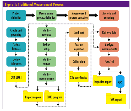
A traditional 3-D measurement process performed with a coordinate measuring machine (CMM) can be summarized by the flowchart seen in figure 1 below. Note the key elements:

• Product definition. This is the stage at which part geometries, features and tolerances are defined. The output is a 3-D computer-aided design (CAD) model, complete with dimensions and geometric dimension and tolerancing (GD&T) information.
• Measurement process definition. This step identifies the measurement equipment and sensors that will be used to make the measurements, how they will be set up and which characteristics will be measured. The end result will be an inspection plan, operator work instructions and, in the case of automated inspection, an automated inspection program for a CMM or similar device.
• Measurement process execution. The CMM measures part features and outputs the x, y and z coordinates of each measurement.
• Analysis and reporting. Finally, the measurements are analyzed and compared to the specification limits. The part is determined either to have passed or failed the inspection. All relevant data are then output as a report and, possibly, as input into statistical software for further analysis and trending.
Although the number of key characteristics to be measured varies, this workflow is based on identifying and measuring these characteristics, and providing an analysis report of the resultant data.
For first-article inspection, this means inspecting all of the dimensions that can be determined on a drawing. This usually occurs at the beginning of the production cycle, and its objective is to validate the repeatability of the process. The measurement process requires a significant investment of time to take all the measurements. Due to such comprehensive measurements, first-article inspection is expensive and can have a huge effect on time to market.
Conversely, during regular production, which is geared to monitor the process and to validate key features, fewer characteristics are inspected. In both cases the measurement process focuses on identifying the characteristics to be measured and analyzed.
In today’s manufacturing environment, with its ever-decreasing development time and ever-increasing call for product customization, this system has become too cumbersome. Too much time is spent inspecting superfluous features, increasing both the first-article inspection cycle time and cost, and causing production inspection to either take too long or to inspect too few product samples to keep up with demand. To address this problem we need to ask questions:
• Why spend a long time using a CMM to inspect characteristics that might be within design tolerances?
• Why spend a long time analyzing all the inspection data to determine which characteristics are in or out of tolerance?
• How can the inspection time be accelerated while measuring the entire object?
One solution is to increase measurement speed and decrease the number of characteristics being measured. Determining the subset of characteristics to be measured requires answering the following questions:
• How do you determine which characteristics to measure and which to ignore?
• What if some of the out-of-tolerance characteristics aren’t in the inspection plan?
• Can characteristics that are out of tolerance be related to improper part alignment during measurement, and thus prove not to be out of tolerance at all?
Laser or structured-light scanners capture the entire shape of an object quickly and accurately. This capability can be used during the measurement process to dramatically reduce--in some cases by as much as 95 percent--the time needed to collect dimensional data of an entire object and to compare the object’s geometry against a nominal CAD geometry. Even though millions of points are captured to fully and accurately describe the shape of the object, the process takes only a few minutes.
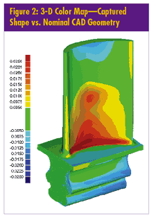
DSSP software quickly performs a 3-D comparison of the captured shape against the nominal CAD geometry and displays the results on a computer screen using color maps, such as the map depicting a turbine blade in figure 2 below.
 Areas whose color departs from green are those where the actual geometry departs from the nominal geometry. The darker the red, the further the measurement deviates from the nominal geometry in a positive direction (more material), which ultimately will result in a wider blade. Conversely, the darker the blue, the further the deviation from the nominal geometry in a negative direction (less material), thus resulting in a thinner blade. The above analysis can easily be achieved, typically in less than 30 minutes, including setup, scanning and analysis. Areas whose color departs from green are those where the actual geometry departs from the nominal geometry. The darker the red, the further the measurement deviates from the nominal geometry in a positive direction (more material), which ultimately will result in a wider blade. Conversely, the darker the blue, the further the deviation from the nominal geometry in a negative direction (less material), thus resulting in a thinner blade. The above analysis can easily be achieved, typically in less than 30 minutes, including setup, scanning and analysis.
From the first analysis of comparing the captured turbine blade shape described by millions of points, further analysis can follow, including:
• GD&T analysis to locate the deviation from a datum reference frame
• Thickness analysis to locate critically thin walls
• Airfoil analysis of main characteristics such as chord length, trailing edge radius and twist
With this new method, subsequent measurement and analysis can concentrate primarily on out-of-tolerance characteristics. Even when measuring those characteristics on a slow but highly accurate CMM, a great deal of time is saved because this secondary measurement focuses only on trouble areas. Eliminating measurements saves time and increases productivity.
Another major advantage offered by the DSSP technique is its ability to help engineers quickly interpret measurement data and shift from data collection to information analysis.
Analysis of the resulting inspection data can drive change and process improvement. From information in inspection reports for failed parts, analysts can determine the causes of out-of-tolerance measurements and, more important, the corrective actions necessary to restore the process to producing parts in tolerance.
Although many software packages (such as those from Geomagic, Metrologic, Verisurf, PC-DMIS, Delcam and Unigraphics/Valisys) allow data from a 3-D measurement device to be compared directly to the CAD model, they have not yet completely penetrated the manufacturing environment. Many shops still use the traditional technique of storing inspection data in databases and spreadsheets. Engineers then spend hours, days, and sometimes weeks retrieving and massaging those data to understand and compare them to CAD data. They then document the analysis using tools such as Microsoft Word or PowerPoint.
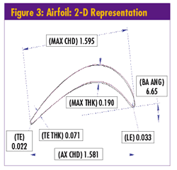
By capturing the full shape of an object and generating graphical reports that are easy to interpret, DSSP enables engineers to focus quickly on manufacturing issues, providing information to the decision makers at the right time, in the right format and rich in content rather than in useless amounts of data. In addition, color maps of 3-D deviation, GD&T analysis, more traditional 3-D dimensioning, and wall-thickness analysis can be combined with 2-D sectioning and dimensioning to more easily correlate with blueprinting and ballooning, as seen in figure 3.
 DSSP’s ability to easily produce digital and graphical data, and then automatically compare them to CAD data, eliminates the manual data processing step and minimizes the time it takes to detect a process fault and correct it. DSSP’s ability to easily produce digital and graphical data, and then automatically compare them to CAD data, eliminates the manual data processing step and minimizes the time it takes to detect a process fault and correct it.
Thus far, this article has introduced three major points:
• Traditional measurement techniques that are CMM-dependent are based on a workflow that identifies the features to inspect and analyze, regardless of whether they’re in or out of tolerance.
• DSSP techniques can capture shapes of objects quickly, identifying critical dimensional areas.
• DSSP reporting provides valuable, interpretive information to the decision maker.
How can modern measurement techniques use these advantages, merging them into an efficient, faster and more economical measurement process? Rather than measuring all characteristics, the process should measure and analyze only the characteristics that are needed, i.e., those critical measurements that are out of tolerance and need to be corrected either by changing the process or remachining the part.
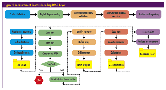
With this approach, the traditional measuring steps are rearranged to add a DSSP layer. Compare figure 4 below to figure 1. Note that the main difference between the two processes is the addition of the DSSP column that defines how the entire part is quickly scanned and compared to the CAD model. If the part is out of specification, it can move along in the measurement process using whatever measurement device is appropriate, but measuring only those characteristics that are out of tolerance. This results in a faster time to market and a cheaper inspection process.

Square D, a subsidiary of Schneider Electric, is perhaps the most recognizable brand of electrical distribution and industrial control products, systems and services in the world. The company employs 17,000 people in the United States, 300 of whom are responsible for designing and inspecting parts. Like most companies that manufacture a large number of products, Square D uses 3-D CAD/computer-aided manufacturing (CAM) tools that significantly speed up the design process and reduce development costs.
The company performs first-article inspections on all its parts, which involves examining every feature and dimension for flaws or deviations from the original model. Typically, more than 1,000 dimensions are checked based on 2-D drawings, making the process time-consuming, tedious and expensive.
For example, a plastic molded cover for a circuit breaker requires that 1,295 dimensions be measured. Because Square D outsources the measurement process to suppliers, the cost of inspecting a dimension is accurately known: $12.50 per dimension inspected using a CMM. Using a CMM only, the total cost of the first article inspection of the plastic covers would be more than $16,000.
Square D instead used DSSP techniques: an LDI scanning head mounted on a CMM machine, and Geomagic Qualify software to analyze the capture of point clouds. The fast scanning process and 3-D deviation indicated to the engineers that only two measurements were out of tolerance. To be prudent, Square D decided to further inspect the two measurements using a traditional CMM--one that provides higher accuracy. In addition to the financial savings, the total inspection process was also shortened from three weeks to two days, allowing Square D to quickly approve the plastic mold and ship the parts much faster.
A new measurement process based on DSSP technology is complementing, improving and revolutionizing the traditional CMM-based measurement process.
Using laser-based technology and/or white-light technology, the measurement process is not only much faster but also provides a more complete description of the shape. Out-of-tolerance areas are graphically displayed with deviation color mapping, allowing for quick and easy identification of critical out-of-tolerance areas. Only for this critical area is a more in-depth inspection process required along with proper inspection planning.
The paradigm shift in inspection planning and execution provided by DSSP technology allows customers to measure what’s dimensionally critical, saving time and money by not inspecting what’s either in tolerance or not critical.
Alberto F. Griffa is senior product manager at Geomagic Inc. He is responsible for the Geomagic line of inspection products, which includes Geomagic Qualify, Geomagic Blade and Geomagic Review.
Griffa has more than 15 years of experience in the area of manufacturing, particularly in quality inspection, both in the aerospace and automotive industries. Before joining Geomagic, Griffa spent 10 years at Tecnomatix, where he held a variety of positions in presales, marketing and business development. There, he focused primarily on software for tolerancing, inspection and CMMs. He also served as design engineer in Microtecnica Aerospace and manufacturing manager in S.p.A. Industria Articoli Gomma (SAIAG).
Griffa holds both a master’s degree in mechanical engineering and a bachelor’s degree in aerospace engineering from Politecnico of Turin. |