| by Jack Thornton
It’s no secret that our highly competitive marketplace offers big profit margins for those who innovate rapidly--and big penalties for those who don’t. Yet despite such fundamental motivation, many manufacturers are slow to get their new products into initial production, the critical first step in rapid innovation. Moreover, as production runs become shorter and product changeovers more frequent, these companies face dismal numbers concerning time to market, returns on assets, productivity and even quality.
Real-Time Uses for RTLI
RTLI systems are used by automakers for “gap and flush” checks and “fit and finish” analyses to perform design checks on vehicles coming off production lines, as well as other process control tasks. At General Motors’ design check and vehicle assessment facilities in Warren, Michigan, a team of four skilled tradesmen and one engineer armed with two Romer-based RTLI systems continuously check fit and finish. Their checks cover the many ways in which a car’s exterior sheet metal panels come together.
At various times, the design check team has laser-scanned hinge and door mountings, entire car underbodies and even front passenger areas of luxury cars sold by competitors.
These scans are often color-mapped to show deviations as the surface is described in the GM math model or in a supplier’s CAD system. “Those color maps also show whether any section of the surface is out of tolerance and, if so, how far out,” says John C. Sturgis, design check team liaison engineer and team leader. “That kind of data is very handy for stamping-die rework. For us, this is all about the physical integration of as-designed parts rather than focusing on the dimensional measurements of individual parts.” Those kinds of inspections are always done at the production line and are always referenced back to the math model.
“This is where the math meets the molecules,” says Phil Karas, design check team member.
An early Delcam RTLI system was deployed to inspect 20-ft rotor blades for aerodynamic performance problems at a large U.K. helicopter builder. Laser-scan probing uncovered errors in the composite blades’ helical twists that every other inspection method missed. Managers and engineers believed the problems were much simpler, such as minute bends or sinks in the blades’ surfaces.
The first RTLI system was installed in Japan at a Toyota plant and is still in operation. That was a real-time reverse engineering system developed jointly with Perceptron, systems integrator Tokyo Boeki and Kosaka Laboratories, which makes the Vectoron PCMM arm. |
Back when production runs included thousands of pieces and lasted for weeks, decisions were nowhere near as time-critical as they are today. Inspection delays of a few hours were insignificant, representing a minuscule fraction of the total available time-to-delivery. Such delays were considered a small price to pay for certainty. Now, however, many production runs are in the hundreds or even dozens and last a day at most. The time involved in inspection is critical.
Even in the best lean and flexible manufacturing environments, last-minute delays occur. New methods and processes must be fine-tuned, components tweaked and fixtures adjusted. This generates a huge demand for troubleshooting and root cause analysis, particularly in situations requiring surface inspection, where speedy, accurate and real-time comparisons to design data are a must.
Innovations in surface measurement and inspection offer creative, rapid solutions to some of these problems. For example, real-time laser probe surface inspection (RTLI), an advanced form of noncontact, laser-based scanning, offers fundamental and striking improvements over touch probe contact methods. For starters, the amount of data is several orders of magnitude larger--millions of points instead of a few dozen. Surfaces are painted with points by means of a noncontact laser probe wielded like a digital paint roller. No matter how large or small, surfaces can be minutely inspected. Decision makers no longer need to rely on educated guesses after selecting a few points on a few geometric features.
RTLI systems sort out geometric features in the point cloud and compare them with the CAD file or solid model in real time. This capability is crucial to the decision making required to solve new product problems in machined, stamped or molded parts of metal, rubber, plastic and many other materials, regardless of how their key geometric features or datums are expressed.
With new products’ increasing sophistication, the ability to handle mathematically complex surfaces becomes vital. Many consumer products are ergonomically and aesthetically designed. These go far beyond orthogonal surfaces built of geometric primitives. Although new product dimensions can be verified by touch probe, their surfaces can be thoroughly inspected only with RTLI technology.
The RTLI system discussed here is built on four pieces of state-of-the-art technology:
 A Romer CimCore portable CMM (or PCMM), also called an articulated arm A Romer CimCore portable CMM (or PCMM), also called an articulated arm
A Perceptron Inc. laser scanning probe
PowerINSPECT point cloud processing software from Delcam Inc.
A top-of-the-line laptop computer
The PCMM locates the probed points in 3-D space and can measure to ±16 mm, depending on the size of the arm. Together, a PCMM and laser probe system can measure to ±66 mm (combining scanner and PCMM accuracy).
The laser scanning probe, attached to the end of the PCMM arm, can gather between 15,000 and 25,000 points in 3-D space per second with an accuracy of 50 mm or fewer. Probing is done at rates of 15 to 200 scan lines per second, and each line contains hundreds of points. Employing leading-edge technology, these devices are far advanced over earlier generations of scanners primarily used in reverse engineering.
In addition, contact and noncontact inspection results can be merged into the same file; PCMMs in the leading RTLI systems use touch and noncontact probes interchangeably.
Software must be fast enough for real-time comparisons with the part’s original CAD data or solid model and smart enough to identify any geometric features. To keep pace with today’s laser probes, inspection software should be able to read and process nearly 1.4 million points per minute in real time.
As of late 2004, this means dual processor PCs with two or three gigabytes of RAM, CPU speeds in the gigahertz range and two gigabytes of disk swap space for calculations. Sixty-four-bit processing and the latest versions of Windows XP are strongly recommended.
To ensure thorough integration of all system components, a turnkey solution purchased from all three of these technology leaders is recommended. At this stage of development, some custom integration is still required between the laser probe, the CMM arm and the inspection software. According to Delcam, plug-and-play compatibility for RTLI remains three to five years in the future.
Additional RTLI Players
Other companies in this emerging business include Rainbow Geomagic, InnovMetric, Faro Technologies and several makers of laser scanners and probes such as DataPixel, Steinbichler, Kreon and Metris.
Dimensional measurement systems manufacturers Carl Zeiss IMT, Mitutoyo, and Brown & Sharpe are believed to be readying their own RTLI systems. Some of their efforts are being coordinated through a new standards committee known as the Optical Sensor Interface Standard Committee, which is developing standardized interfaces between CMMs and noncontact optical probes and scanners.
A significant OSIS success is the new DAQ software layer already available from Zeiss’ Wolf & Beck unit. The corresponding interfaces for touch probes are embodied in DMIS, which has been around for nearly 30 years. |
Here are just a few of the benefits of RTLI inspection:
Determining if surfaces truly comply with their geometry. RTLI concerns itself essentially with surfaces, unlike touch probes, which excel at checking against predetermined datums, sizes, tolerance bands and distances between features. But touch probes always leave nearly all of a given surface unchecked. Operators have no choice but to presume or extrapolate that what’s between the points is the same as what was probed.
For some ergonomically designed parts, that’s not good enough. Flat or gently curved surfaces have hidden sags or humps. Subtly curved surfaces (splines, for instance) might or might not match the geometry with which they were generated. Only RTLI can reveal these flaws. The technology is also suited to checking corners and edges inside molds, dies and forming tools.
Measuring despite obstructed lines of sight. This is something laser tracking systems and theodolites can’t do. The infinite rotation of the PCMM arm’s three main joints as well as the small size of the laser scanning heads allow operators to reach over, under, around or behind just about anything. There are no delicate and cumbersome mirrors to align.
Measuring parts in and out of their fixtures. RTLI can even measure parts without check fixtures. With other methods, this is often awkward.
Measuring tiny features. This is best handled with RTLI because it can paint an almost unlimited number of tiny optical points on a surface.
RTLI has three primary competing technologies:
Touch probes. For flat and very large radius curved surfaces, touch probes leave too much surface area uninspected and can miss small but crucial errors. For tiny features, sufficiently small probes would be too delicate. Painting surfaces with points is the key to 100-percent inspection. It’s unmatched for revealing errors in helical surfaces and airfoils, for example.
Dimensional measuring interface specification (DMIS or PC-DMIS). The much- newer PowerINSPECT can compare far larger point clouds with CAD files than DMIS can, especially in real time.
Fixed-in-place CMMs, whether computer numeric controlled or manual. Because they can’t be moved to where inspection is needed, CMMs greatly limit the speed and variety of possible inspections.
Real-time inspection is meaningless, of course, if you can’t measure a part where you make it. An RTLI system’s portability means that inspection has finally moved out of the traditional, isolated temperature- and humidity-controlled inspection rooms, which are dust- and vibration-free, and into the real world.
Despite their extreme precision, the components of RTLI systems are very robust. They’re protected from dust using sophisticated sealing systems in the PCMM arms, the scanner heads and in their hardware interfaces. They’re also protected against electrical spikes and sags as well as electromagnetic radiation from welders. In recent years, laser scanners have come a long way in dealing with surface reflectivity and in rejecting the noise of ambient light, high-pressure sodium lights, tungsten lights, sunlight and even welding flashes. The newest scanners also have a much wider angle of incidence, up to 35° either side of perpendicular (surface normal), which simplifies an operator’s work in confined areas.
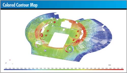
RTLI inspection software generates colored contour maps, sometimes called “weather maps,” which reveal the precise topography of a surface by comparing it to the CAD file from which it was generated. The maps show errors, deviations from specifications and the relative distance of any point on a surface from the edge of the CAD nominal.
The software then maps the errors in an intuitive color scheme. Green is for points in tolerance, red for points out of tolerance on the plus side and blue for points out of tolerance on the minus side. These displays show the corrections needed to maintain tolerances and specifications, a vital process control capability.
RTLI color weather maps are invaluable for troubleshooting and quickly searching out root causes. When the forming surfaces of tools, dies and molds are questioned, the need for inspection goes far beyond touch probe dimensional measurements. Once the tool’s alignment and orientation have been verified dimensionally, RTLI can zero in on the key surfaces of any inspected product.
While touch probe and contact systems remain the preferred way to address the majority of factory floor problems, laser probing’s overriding benefit is the prodigious amount of data produced. Millions of 3-D coordinate points can be gathered in just a few minutes. While that’s a limited advantage over prismatic parts, the technology is of huge value with sculptured surfaces.
Adopting new technologies typically reaches a tipping or inflection point three to five years after introduction. This means RTLI will begin to make previous surface inspection methods obsolete by 2006. RTLI’s intuitive ease of use will only accelerate this trend.
A change in any physical dimension of a product--a manufacturing tolerance, for example--requires dozens of individual decisions on product modifications and tooling adjustments. Tackling these without analysis based on surface measurements and CAD file comparisons will soon become unthinkable.
Jack Thornton is principal of Mindfeed Marcomm, a marketing communications firm based in Santa Fe, New Mexico, which specializes in feedback from users of software in inspection, simulation, finite element analysis, machine tool programming and inventory optimization. Thornton founded Mindfeed in 1993 following a career of more than 20 years in marketing, public relations and industrial journalism.
|