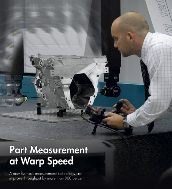
| by Barry Rogers
The cost of quality is viewed as the top nonvalue-added activity in manufacturing operations. In their efforts to run leaner and faster, manufacturers seek to reduce, shorten, or eliminate post-process quality operations that increase the work-in-process burden. Complicating matters is the fact that manufacturers must perform more inspections to meet ever-higher precision and ever-tighter tolerance requirements. They must check more parts and features more often, and gather more data points per feature more quickly, to monitor and control the manufacturing process. Faster inspection is especially vital on complex, high-value parts with many critical features. For these products, metrology data can flag problems or identify negative trends to prevent the production of out-of-specification parts.
To address this dilemma, manufacturers are looking for a way to increase coordinate measuring machine (CMM) throughput. The faster they can measure parts, the better they can maintain control of their processes and optimize production efficiency.
Makers of complex, high-value parts are finding that multi-axis processing can speed throughput, reduce work in process, achieve higher levels of automation, and elevate quality by reducing process variation and error-stacking. On the machining side, five-axis and multi-tasking machines allow done-in-one processing with fewer setups and less part handling.
However, inspecting complex parts can be a bottleneck to faster processing. These inspections, which require form measurement of critical geometries for functional fits, can demand many thousands of data points. Traditional point-at-a-time touch probing is far too slow and provides limited data density, while noncontact 3-D scanning is fast but not accurate enough. That leaves contact scanning on a CMM, which can provide the desired accuracy and continuous point taking, but only by keeping a governor on machine speeds.
Some manufacturers have found a solution to the bottleneck in revolutionary, ultra-high-speed, five-axis CMM measurement technology using an innovative, two-axis, infinite-positioning probe head mounted to the Z-axis quill to perform most measurement tasks. The system can be retrofitted to existing three-axis CMMs to upgrade them to five-axis measurement capability.
Historically, speed has been the physical limiter on accurate CMM measurement. Higher acceleration rates and rapid axis changes induce inertial errors that cause deterioration in measurement accuracy. The only way to maintain acceptable accuracy in three-axis scanning has been at the expense of measuring speed. Consequently, high-accuracy, three-axis CMMs typically scan at rates of five to 15 mm/sec. CMM inspection has been stuck in that speed range for more than two decades.
Depending on the part geometry, the new high-speed scanning technologies can raise scanning speeds to as much as 500 mm/sec -- that’s 100 or more times faster than many CMMs. Renishaw, inventor of the touch-trigger probe that made CMM inspection practical, attacked the CMM speed issue on multiple fronts. Its high-speed scanning system delivers ultra-high scanning speed and measurement flexibility while avoiding the speed-vs.-accuracy compromises inherent in conventional CMM measurement.
Dynamic scanning’s speed, flexibility, and accuracy have brought exceptional performance to a wide range of scanning measurement applications, including circle, helix, sweep, and gasket scanning, and, where required, rapid single-touch routines.
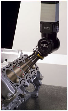
High-speed, infinite-position measurement has enabled new approaches to probing. For example, helical scanning can greatly speed the measurement of bores while generating thousands of data points to determine roundness, concentricity, or taper, as seen in the images at the left side of this page and above. A sweeping scanning routine can capture the edge geometry of a turbine blade by tracing back and forth from each side of the blade.
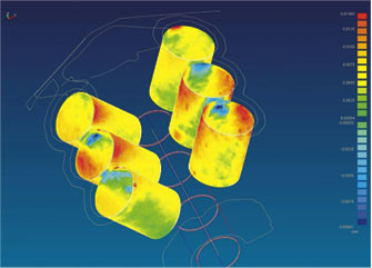
A leading automobile manufacturer has assessed the system’s massive data-capture capabilities to measure engines for wear analysis and cylinders for their deviation in spatial orientation. The captured data are compared against new-engine specifications; colors are assigned to the wear deviation to generate graphics similar to a thermal scan, as seen in the image below.
The technology involves multiple innovations -- a probe head with self-contained rotating and swiveling action, five-axis machine control, and a stylus with internal laser-position sensing. The key features of the technology are as follows:
• Dynamic measuring head. A two-axis, infinite-positioning head performs most of the measurement work. A 3-D measuring device in its own right, the head minimizes CMM motion and associated inertial errors, and its low-mass, low-inertia design allows ultra-high-speed data capture -- up to 4,000 points/sec compared to 200-300 data points/sec with conventional scanning.
Although the head provides the capability for simultaneous five-axis movement, its greatest advantage is that it can limit CMM motion -- where motion is required at all -- to what a CMM is designed to do best: move at constant velocity while measuring. Lighter and more dynamic than the CMM, with a significantly better frequency response, the measuring head can quickly follow changes in part geometry without introducing harmful dynamic errors caused by inertia when moving a CMM’s more massive linear axes. The dynamic head design also collapses measurement uncertainty to achieve high accuracy despite the phenomenal increase in speed. Measurement occurs within the head just a short distance from the point of part contact, rather than at distant CMM axis encoders. These encoders are separated from the point of contact by connected machine members and components, each contributing its own "noise."
Two rotary drives -- 360° in the horizontal plane, and 120° in the vertical plane -- provide wrist-like action for infinite adjustment to the part surface while measuring. The head features greater bandwidth than a conventional CMM, enabling accurate, high-speed following of the path demanded by the software. Proprietary technologies -- including hard-gold slip-ring contacts, high-resolution, 0.08 arc-second rotary encoders, and spherical air bearings -- minimize friction and wear, enable high-dynamic response, and provide a stiff metrology platform for reliable positioning accuracy at high speeds and acceleration forces.
The REVO head differs from indexing heads available as CMM options. Indexing heads provide adjustments at 2.5°, 5°, and 7.5° increments, but the heads must be unlocked, rotated into the desired position, and then locked again before measuring. This slows the measurement process and complicates programming and calibration. The infinite-positioning head measures without having to return to a zero position, thereby maintaining surface contact and precisely capturing fine changes in complex part geometry.
• Five-axis control. Proprietary software drives the dynamic measuring head and synchronizes its motion with the linear moves of the CMM, providing five-axis continuous measurement. The head rotates and measures simultaneously to reduce delays in moving from part feature to part feature, thereby shortening cycle time. Look-ahead algorithms profile the probe path as a single continuous motion. The software features error-mapping routines that compensate for the effects of geometry, temperature, and machine dynamics.
• Laser-measurement stylus. An innovative engineering solution provides a low-mass, low-inertia stylus that deals with the bending stresses of rapid direction changes, high acceleration, and inertia forces. Unique tip-sense probing features a hollow-tube stylus with an internal laser to measure controlled tip deflection. A laser beam is directed from its source in the probe body, down the hollow stylus to a reflector at the stylus tip. Bending deflects the return path of the laser beam, which is received by a position-sensing detector (PSD) in the probe body. Software algorithms combine PSD input with head geometry and CMM axis scale, calculating the stylus tip position in space. Laser light measures faster than the probe can move, so the position can be continuously determined while the stylus tip is scanning. The probe delivers 1 µ m accuracy at 250 mm from the axis of rotation at 500 mm/sec. Laser measurement enables longer styli -- up to 500 mm -- with little degradation in accuracy.
Tip-sensing probe heads require only a single tip location calibrated to be accurate at all angles of rotation, which typically saves several hours during a setup routine. Using a table-mounted sphere, the simple calibration technique determines the head and probe geometry, allowing measurement in any position after a single calibration. The system can save the equivalent of days of calibration time per month and ensure maximum availability of the CMM.
• Universal controller. A universal controller provides a digital processor for all CMM functions, which are crucial to data management at ultra-high scanning speeds. The universal controller allows the measurement system to be retrofitted to existing CMMs. As part of its design, the controller features an I++DME open interface, providing cross-platform compatibility with major measurement software packages.
The REVO head and controller combination is capable of collecting 4,000 points/sec, and accurately locating the probe tip while measuring at 500 mm/sec.
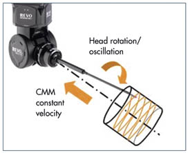
The two illustrations below show how the head can quickly perform a complex helical scan.
Following an extensive preview and testing period, the Renscan5 system is being implemented by world-class manufacturers of critical parts. Early applications have demonstrated tremendous time savings, as follows:
• Jet engine blisk. This application allowed a 922-percent throughput improvement. The inspection sequence comprised nine section scans of the airfoil profile, eight longitudinal scans of the blade, two scans of the root profile, and one scan of the annulus profile.
Three-axis scanning at 10 mm/sec:
-- 46 min (1 blade)
-- 22 hrs, 14 min (all 29 blades)
Five-axis dynamic scanning at 500 mm/ sec:
-- 4 min, 30 sec (1 blade)
-- 2 hrs, 10 min, 30 sec (all 29 blades)
• Automotive cylinder head. This application yielded a 680-percent throughput improvement. The inspection sequence comprised 12 valve seats and three circular scans in each of 12 valve guide bores.
Three-axis scanning at 15 mm/sec:
-- 29 min, 13 sec
Five-axis dynamic scanning at 400 mm/ sec for valve seats, 50 mm/sec for valve guide bores:
-- 3 min, 42 sec
• Automatic transmission valve body. This application created a 155-percent throughput improvement. The inspection sequence comprised 12 holes with 6-mm diameters, six holes with 5-mm diameters, 25 points on the gasket face, 45 spool bores, three shot scans on the gasket face, and six points on the spool face profiles.
Three-axis scanning at 15 mm/sec:
-- 18 min, 5 sec
Five-axis dynamic scanning at 500 mm/sec:
-- 7 min, 5 sec
Five-axis dynamic measurement technology allows manufacturers to check parts more often, check more features, and take more data points per feature while producing and documenting parts to ever-tighter tolerances. The technology generates hard, accurate numbers based on actual part contact and allows precision not possible with noncontact scanning. Providing far more data points than ever before, dynamic scanning allows better process control and generates analytical data for design improvements. Speeding part measurement can significantly reduce work-in-process and allow manufacturers to realize greater value and productivity from their CMM investments.
An authority on dimensional precision and quality control in machining operations, Barry Rogers started his career in tool and die making with Honeywell and John Deere, then moved into the metrology field with LK Tool USA, manufacturer of coordinate measuring machines, where he rose to general manager of the LK-Cincinnati Milacron Tech Center in Detroit. In 1988 he joined Renishaw, a global leader in inspection probe and machine calibration technologies, where he is presently national sales and marketing manager.
|