Noncontact 3-D measurement technology enters a new era.
__________________________________________
by Ron Gershon, Ph.D., and Meny Benady, Ph.D. Various industrial
applications exist that require highly accurate measurement of free-form objects in a wide range of settings. In the automotive industry, for example, these measurements can be used for design,
body-assembly of engineering prototypes, reverse engineering, quality control of parts, assembly in production, measurement within assembly lines and final quality assurance. New market
requirements, such as a greater number of new car models, a shorter life term of each model and shorter time-to-market, require quick ramp-up times and engineering processes, increased production
flexibility, and smaller production batches. For these purposes, various techniques and methods of 3-D part measurement have been introduced and employed in industrial environments over the years.
These 3-D measurements -- which acquire large data sets in a short time, and analyze and visually display the data -- are getting more and more attention from process engineers who
understand that these systems will play an increased role in automotive engineering to achieve the goals set by the new market trends. A new proprietary technology for noncontact 3-D measurement
is insensitive to vibrations and most industrial lighting problems and is suitable for working directly on the shop floor.
Existing 3-D measurement methods Contact-based techniques (such as the use of coordinate measuring machines) have largely replaced manual measurement methods, which are
typically based on the use of hand-held tools to compare parts to precisely machined templates. In general, contact-based techniques can achieve high accuracy rates and are suitable for a wide
range of measurement applications. However, these methods offer notoriously low measurement throughput because they involve mechanical movement from one measurement point to the next. As a
result, they collect only sparse data, leaving many critical areas unverified. CMMs capable of measuring large objects are themselves very large and cumbersome in production environments.
Furthermore, they must be housed in special controlled-environment rooms that protect against temperature variation and vibration. Traditional noncontact optic methods include structured
light using moir� patterns, laser scanners and trackers, and photogrammetry-based techniques. These methods generally achieve higher throughput than contact methods. However, they normally
achieve lower accuracy rates, and each method has specific disadvantages that limit its use. Solutions based on laser trackers, where reflective hemispheres are operator-scanned around a
feature to reflect a laser beam back to a measuring device, achieve higher accuracy on some surface types but are operator-dependent. They require many types of attachments per type of feature,
do not produce dense enough data and are essentially contact-based. Laser scanners, laser radars and structured-light technologies, such as the use of moir� patterns, require multiple
sequential snapshots, thus limiting them to applications in which time-varying changes are minimal. Therefore, they're not suitable for areas in which vibrations are present, such as
production-line floors. Photogrammetry-based systems, specifically those which require placing targets (i.e., special markers) on the measured parts, can achieve high accuracy levels but
can only be used for measuring specific target points. They're also unsuitable for dense surface scanning and usually require intense manual intervention of operators. New technology New technology combines the high-speed data acquisition of high-resolution CCD cameras with indirect photogrammetry, in
which targets are placed in fixed locations in the background, with sophisticated 3-D reconstruction algorithms. This technology can detect and measure the targets accurately, acquire and
reconstruct images of the object in a fast and accurate fashion, and stitch tiles together. In addition, the robust system enables the measurement of untreated, shiny metallic and plastic parts
under different working environments, such as factory shop floors. Reconstruction of 3-D structure from multiple 2-D images
The reconstruction process is based on the structure-from-motion principle for extracting 3-D shapes from multiple 2-D projections using a pinhole camera model (or "3-D from 2-D"
geometry). Briefly, given two or more views of a set of 3-D features, the corresponding 2-D features are first brought to match each other. The relative locations of the camera are then recovered
from these matches, and, finally, the location of the 3-D features are recovered by triangulation. In other words, the inversion process -- going from 2-D feature locations across multiple views
to the corresponding 3-D feature locations -- requires two basic ingredients. The first is the ability to locate accurately image features from the local brightness distribution of each image and
accurately match those features together, across multiple images, referred to as the matching process. The second is the ability to extract the relative locations of the cameras from the matching
2-D points. The challenges in this process are twofold. First, the matching process is constrained by the geometry because the images are not arbitrary but rather are produced from the
same 3-D object. Therefore, combining photometric principles (e.g., modeling the change of brightness distribution across images) and geometric constraints enables a more accurate computa-ion of
the matching process. Second, two families of parameters govern the relative camera locations: the internal camera parameters and the external parameters describing the rotation and translation
in 3-D space between the camera coordinate systems. This process generates a cloud of points from one take of three cameras; it's also referred to as a "tile." Because the field
of view represented by a single tile is usually smaller than the size of the object to be measured, the process is repeated for as many tiles as are required to cover the object. Special targets
aid in the tile stitching. The targets are mapped in advance to allow alignment of all the tiles. This stitching, and the measured targets, are combined into an alignment procedure that allows
the establishment of a common coordinate system between different pieces of data, such as the tiles among themselves or alignment to a predefined CAD model of the object in question, or any other
coordinate system used by the manufacturer. Because the system simultaneously takes a single split-second image from each camera to measure the surface of an area, it doesn't suffer from
environmental vibrations. In addition, the system combines individual areas of the part with targets that are physically attached to the part. Therefore, because the targets are attached, any
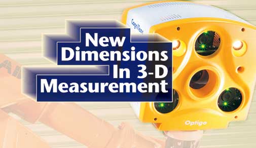
movement or vibration of the part is matched by the system and will not affect the measurement. The Optigo systems
CogniTens 3D Vision Systems built this new technology into its Optigo noncontact 3-D measurement systems. The systems measure and reconstruct free forms of different sizes and materials
(e.g., clay models, and plastic and metal parts) in a single operation. The digitized data collected from 2-D image sets is accurately processed (in real time) into a 3-D model to an accuracy of
20 microns, obtaining very large data sets of hundreds of thousands of points in a single shot. Analyses of the 3-D measurements include highly dense coordinates of an object's surface,
cross-sections, features such as holes and slots, and object edges. Various accuracies are available on one platform, with easy-to-use, on-the-fly exchangeable lenses. Local average accuracy
varies between 20 mm and 40 mm, and standard deviation varies from 15 mm to 35 mm, depending on field of view. The system's technology possesses several important features that enhance its
performance considerably:  Robust image acquisition and processing mechanisms, which allow the acquisition
of shiny surfaces (such as finished metallic surfaces) without the need to treat them with matte paints or dulling spray Robust image acquisition and processing mechanisms, which allow the acquisition
of shiny surfaces (such as finished metallic surfaces) without the need to treat them with matte paints or dulling spray
Sophisticated illumination that enables the acquisition of homogeneous surfaces
with no texture (such as car roofs) in a single shot, while providing the necessary data for the reconstruction process 3-D measurement using a single free-moving optical head, which allows for easy
operation and simple traversal of the object. This process is complemented by the stitching of tiles to form complete models of objects. Practically, this is performed
with high-resolution, hand-held photogrammetric mapping cameras designed for mapping targets on the part or on the fixture and provide high-accuracy tile alignment
for parts, which require more than a single-tile measurement. To map, several photos are taken with the mapping device, covering the part from different angles. The
pictures with the coded targets are downloaded, and the Optigo software calculates their position. The resulting target coordinates are used to align the individual tiles
measured by the system into a single global coordinate frame. This allows the system to measure objects of practically any size, at high- accuracy levels. The system is resilient to fluctuations in working environments, such as factory
floors. It can operate in areas with varying temperatures, under most industrial lighting (e.g., fluorescent, sodium, metal-halide or mercury) and in vibrating
environments. A built-in temperature sensor automatically indicates the necessity for new calibration when temperature fluctuates on the shop floor. After taking a single
image, which requires only one second, calibration is fully automatic. Applications and outputs
This technology is useful in numerous applications. Examples of the system's capabilities in industrial applications include: Automotive body assembly. Manufacturers operating assembly lines seek to fix
repetitive problems, such as deviations from the design, during the production phase. In addition, because the ramp-up of a production line is a long process, there's a need
to shorten this process to get a line up and running in a shorter period. The user can pinpoint problematic welding stations or press machines and point out the exact
location where the deviation from the original design takes place. Due to the fast acquisition and analysis, the system gives a quick resolution to existing or anticipated
problems, thus shortening the ramp-up time of various assembly lines.
Quality assurance of sheet metal in production. Various quality assurance procedures are employed within the production process. In addition, when problems
arise in production, some tooling changes are necessary, often requiring verification of the changes to take place. Parts measurement is performed on the shop floor as the
parts come out of the manufacturing process; the system also provides a quick indication of the part quality and the quality of the tools that produced them. Mold-and-die development in production engineering. Production engineering often
requires the examination and verification of molds and dies. These tests sometimes take weeks to perform because they're based on numerous correction cycles. Optigo
systems help identify problem sources for the first time while covering the entire surface of a given part. This coverage enables speedy measurement of parts, reducing
the number of correction cycles required to one or two cycles, sometimes saving six to eight weeks of die-and-mold development in production engineering. Design-scanning of full-scale models. To design part models, designers need to
view first-hand what the parts look like, so the dense scanning of complete body surfaces is necessary. This requires dense and accurate part measurement, which is
traditionally performed by contact techniques. However, Optigo systems provide high-quality, dense data in less time, and automate model scanning in such a way that
they eliminate the need for touch-ups and improves the design process's accuracy and speed. Measures of progress
This novel approach to noncontact 3-D measurement suitable for the production floor of industrial environments is based on advanced machine vision technology in
which high-resolution image acquisition is processed in a fast and accurate way, thus providing a dense cloud of points that represents the structure of the viewed object.
These points are then used to construct surfaces or provide data for comparison of the real part with its original CAD model. The system, targeted to work on the shop
floor and in the toughest industrial environment, is equipped with high-grade components (e.g., optic fibers instead of cables). Typically, the system price is higher
than for competing technologies that can be used only in controlled laboratory environments. The technology also offers: Measurement on the production line or near it Simultaneous single-point and full-surface measurement Accuracy comparable to that of a CMM There are several benefits to the system: Reduction in the number of rejected parts Better quality and higher sampling rates Better process control Detailed feedback to production engineering The examples presented here illustrate the various tools for investigation and analysis
of dense data sets representing industrial parts. The tools are easy and intuitive to the operator and provide valuable information on specific parts and on process trends on
the production line. This information can reduce waste in material and processing and correct production errors right on assembly lines and production floors. About the authors Meny Benady, Ph.D., is vice president of business development for CogniTens 3D
Vision Systems Ltd. Ron Gershon, Ph.D., is manager of CogniTens Algorithms. To contact the authors, or for more information, e-mail mbenady@qualitydigest.com . |