| by Kennedy Smith
In the world of nondestructive
testing, there are plenty of technologies to choose from.
They include visual and optical inspection, penetrant testing,
magnetic particle testing, electromagnetic testing, radiography,
acoustic emission testing, leak testing and ultrasonic testing.
The common benefit of using any of these methods is that
you don’t destroy the material you’re inspecting.
With the emergence of advanced computer technology, many
of these testing methods have become more popular in industries
ranging from petrochemical to automotive. One method that’s
receiving much attention is ultrasonic testing.
During the last 10 years, ultrasonic testing has boomed.
Experts suggest that a surge in information technology has
increased ultrasonic testers’ capabilities while decreasing
their price--making ultrasonic testing available to many
industries that had previously avoided it. In fact, many
experts agree that ultrasonic testing is the up-and-coming
nondestructive technology.
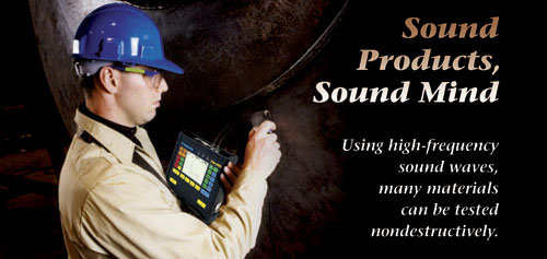
Most people are already familiar with ultrasonic testing
as it relates to medicine, such as women who have ultrasound
tests during pregnancy. In a nutshell, ultrasonic testing
entails directing high-frequency sound waves toward a material
to detect changes in material properties. “A piezoelectric
transducer is basically excited with a voltage to generate
a sound wave,” explains Dennis Zwigart of StressTel,
which manufactures thickness gages, flaw detectors and bolt
monitors. “The sound is put into the part and reflected
back from something--either the back side of the part or
from a flaw--depending on what’s in the material.
When it reflects back, the operator can process that signal
digitally and determine the thickness of the metal or the
flaw that’s inside the metal.”
Ultrasonic testing for nonmedical purposes works in the
same capacity as ultrasound and began in the years preceding
World War II. With the emergence of sonar (recording echoes
from objects submerged in water), scientists were soon testing
ways in which sound waves could be used to detect flaws
in metals. In the early 1930s, Soviet scientist Sergei Sokolov
became the first person to demonstrate through-transmission
for flaw detection in metals. Other scientists expanded
upon Sokolov’s ideas to create the beginnings of what
would become modern ultrasonic testing technology.
During the 1970s, ultrasonic testing had advanced to the
point that it could detect very small imperfections within
metal. Although this was advantageous for technicians working
on flaw detection, manufacturers found themselves rejecting
many parts that were once considered passable. Out of this
unexpected disadvantage emerged fracture mechanics and other
laws to predict fatigue in materials.
Presently, some of the most common applications of ultrasonic
testing are in thickness gaging and flaw detection.
The list of industries that utilize ultrasonic is long.
“We have customers in petrochemical, fossil and nuclear
fuels, ship building, mining, automotive, construction,
primary metals, aviation and so forth,” notes Zwigart.
Materials that cannot be tested ultrasonically include
anything that can’t transmit or allow sound waves.
“For example, say I bond two pieces of metal together
and want to make sure they’re bonded correctly,”
suggests Larry Culbertson of Mitchell Labs, which performs
ultrasonic testing for a number of industries. “If
there’s an air pocket between the two pieces, the
sound waves will not travel through them.”
There are a variety of techniques used in ultrasonic testing.
They include:
 Pulse-echo. This method uses short pulses of sound
that travel through the part to either locate a crack or
the back side of the part. It’s suitable for flaw
detection or thickness testing. The time it takes for the
sound to travel through the part and bounce back is calculated
using the simple equation, d = vt/2 where d is the distance
from the surface to the discontinuity, v is the velocity
of sound waves and t is the round-trip transmit time. The
user moves a transducer over the surface of the part, and
the tester will record the echoes.
Pulse-echo. This method uses short pulses of sound
that travel through the part to either locate a crack or
the back side of the part. It’s suitable for flaw
detection or thickness testing. The time it takes for the
sound to travel through the part and bounce back is calculated
using the simple equation, d = vt/2 where d is the distance
from the surface to the discontinuity, v is the velocity
of sound waves and t is the round-trip transmit time. The
user moves a transducer over the surface of the part, and
the tester will record the echoes.
Angle-beam. The angle-beam method has to do with
the type of transducer used. An angled sound path can be
used to better detect flaws within a material. This is explained
further in the next section.
Crack-tip diffraction. This method is used to
determine the length of cracks within a material. If an
angle beam is scanned over the surface of the part, the
lowest point of the crack will appear as the weakest signal
because the distance traveled by the sound wave is longer.
Automated scanning. Automated ultrasonic scanning
systems are often used with the part and transducer fully
immersed in water. This enables consistency of measurements
because the coupling agent’s (i.e., water’s)
properties remain constant.
Another newer technology is laser ultrasonic inspection,
which utilizes laser beams to generate ultrasound and collect
signals. Advances in transducer technology have lead to
the development of the air-coupled ultrasonic technique.
These systems allow sound waves to be transmitted through
air and remain strong enough to penetrate the part and return
a signal.
The three major components of an ultrasonic tester are
the transducer that emits sound, a computer display to show
results, and the pulser-receiver, which acts as a kind of
translator between the transducer and display. The pulser
portion of the pulser-receiver generates electrical pulses,
which the transducer converts to sound waves. The receiver
portion of the pulser-receiver amplifies the ultrasonic
pulses, coming from the part through the transducer.
Ultrasonic testing relies on the transducer used to emit
sound. The ceramic piezoelectric transducers generate electrical
impulses and change them into acoustic energy, and vice
versa. “They create mechanical wave forms that go
through the part and change the returning pulse echo from
mechanical back into electrical so that the scope can read
it,” says Culbertson.
There are two major types of transducer: contact and immersion.
Contact transducers, as illustrated on page 31, utilize
a coupling material, such as water or oil, to smooth rough
surfaces and prevent air gaps from manipulating the results.
.jpg)
Immersion transducers don’t come into contact with
the component they’re measuring. Instead, they operate
in a liquid. The watertight effect eliminates the chance
of air pockets affecting results. “We use quite a
bit of immersion in the lab,” says
Culbertson. “With a transducer you can’t inspect
in the near field. With an immersion transducer, you use
water to differentiate the near field and the far field.”
.jpg)
The near field is an area of space in which the sound
waves are not uniform. The ultrasonic beam is more uniform
in the far field, where the beam is spread out in a pattern
originating from the center of the transducer. The variations
that occur in the near field eventually change to a smooth
and declining amplitude, at which point the far field begins.
(See page 32.)
Other transducer types follow:
Dual-element transducer. This transducer uses a
pitch-and-catch effect. “It’s got two elements,”
explains Culbertson. “One is sending the signal, and
one is receiving it.”
Angle-beam transducer. This transducer can be either
contact or immersion. Shear wave is anything other than
zero degrees. For example, if you’re thickness testing,
you go straight into the part. An angle beam will measure
at different degrees. “It’s used when you’re
looking for defects that are neither parallel nor perpendicular
to the part,” notes Culbertson.
.jpg)
Delay line transducer. This contact transducer
contains a plastic wedge between the transducer and the
part being measured. Basically, it eliminates the near field.
High-frequency transducer. Transducers use frequencies
from 0.5 MHz all the way up to 25 MHz--and sometimes up
to 50 MHz. The higher the frequency, the more sensitivity.
Normal incidence shear wave transducer.
This type of transducer emits shear waves directly into
the material without having to use an angle-beam wedge.
There are three ways to display information collected
from an ultrasonic tester. They’re known as A-scan,
B-scan and C-scan. The A-scan presentation displays the
relative amount of energy received on the vertical axis
and elapsed time along the horizontal axis. The B-scan display
is a cross-sectional view with travel time displayed along
the vertical axis and linear position of the transducer
displayed along the horizontal axis. C-scan presentations
are used with automated data acquisition systems. The C-scan
displays information along a plane of the image parallel
to the scan pattern of the transducer. Gaps in the scan
pattern represent defects within the material.
Because of advances in ultrasonic technology during the
last 10 years, the method is becoming more popular with
manufacturers in all industries. “Nondestructive testing
embraces different types of inspection, and the high end
of that is X-ray testing,” notes Zwigart. “However,
X-ray testing can be expensive. You need highly skilled
people, and in some cases, it can even be dangerous. Ultrasonic
testing allows manufacturers to use similar techniques without
the cost of buying expensive equipment and training technicians.”
Culbertson agrees. “The equipment has become more
sophisticated in the last 10 years,” he says. “There
are a lot more features in the equipment, and it has become
small, lightweight and much less expensive. Ten years ago,
you were looking at an instrument that maybe cost $15,000
and it probably weighed 20 pounds. Today ultrasonic flaw
detectors are five pounds, very small, with more capabilities
than ever before.”
With the growing popularity of ultrasonic testing, opportunities
for training have increased as well. “Several universities
now offer nondestructive testing,” notes Culbertson.
“There are also many NDT courses that can be done
by consultants, and through the American Society for Nondestructive
Testing.”
Certification in the field of nondestructive testing is
done through ASNT. Training and certification through ASNT
ensures that the technician is fully equipped to handle
most nondestructive tests. NDT Level III examination is
ASNT’s main examination, which it has offered since
1976. The organization also offers a Central Certification
program, which tests for competency and experience.
Companies also have the option of certifying their own
technicians based on tests similar to those of ASNT. Most
educational institutions that offer courses in NDT prepare
their students for ASNT certification. “Training is
usually taught multiple times during the year,” says
Zwigart. “People involved in the industry actually
have a lot of different places to go for training.”
(See page 34.)
Some of the many resources available online include the
ASNT Web site at www.asnt.org;
the Online Journal of Nondestructive Testing at www.ndt.net;
and the NDT Resource Center at www.ndt-ed.org.
Schools That Offer NDT Training
Source: NDT Resource Center
|
Kennedy Smith is Quality Digest’s associate
editor.
Much of the material gathered for this article, including
images from which the included tables were adapted, came
from the NDT Resource Center, online at www.ndt-ed.org.
|