| by Guido Rademaker, Ph.D.
The quality control role played by X-ray systems in the nondestructive testing and inspection of electronic assemblies--especially today’s printed circuit boards, densely packed with area array components--is well understood. X-ray imaging is especially valuable in rapid prototyping and reverse engineering applications in electronics, avionics, advanced materials research, casting and other manufacturing industries.
Unlike machine vision and optical inspection equipment, which can image only the surface of samples, X-ray systems penetrate substrate materials to expose hidden features. They are ideal for detecting and evaluating features in complex micro-electro-mechanical (MEMS) and micro-opto-electro-mechanical (MOEMS) devices, such as solder joints on chips, CSPs, BGAs, and µBGAs, and for revealing cracks, voids, delamination, and other crucial component anomalies in prototype electronic assemblies, medical devices and castings during preproduction.
Once a need for X-ray inspection has been determined, the user must decide whether two-dimensional or three-dimensional imaging is best for the particular task at hand. While 2-D X-ray imaging is sufficient in many cases, 3-D X-ray images can reveal complex inner structures in an intuitive format so that anomalies can be viewed in their 3-D positions.
Recently developed systems can toggle between 2-D and 3-D modes with a single keystroke, providing the user with a degree of flexibility and efficiency previously unavailable. In addition, user-transparent, automated image-optimization algorithms are available that optimize image quality in real time for interpretation by the human eye.
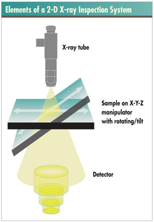
As shown in the figure to the right, 2-D X-ray inspection systems consist of an X-ray source that emits the X-radiation, a fixture or manipulator for holding and positioning the sample being inspected, and a radiation detector that includes electronics to interpret and convert the radiation incident on the detector surface into a 2-D image.
X-ray tubes are available in various configurations and with a range of performance capabilities. “Open” microfocus tubes are used primarily for the high-resolution requirements of electronics assembly and packaging. Multifocus tubes incorporate microfocus, nanofocus and high-power modes all in one tube, providing
multiple-focus ranges to produce magnifications from one to 2,400X. The high-power mode clearly shows high-detail and low-contrast objects, useful for inspection of metallurgic structures in µBGA balls, for instance. It is required for 3-D imaging.
The manipulator is a high-precision CNC mechanical stage that holds and positions the sample. Advanced systems are equipped with precision manipulators that allow the user to orient a sample component or interconnect along as many as six axes: horizontal X and Y axes, a vertical Z axis, an additional Z d axis for detector movement, and respectively rotating and tilting A and B axes. The multiple axes enable irradiation of a part and inspection for defects at multiple oblique angles to the X-ray beam. State-of-the-art manipulators can vary the speed of directional and rotational motion to meet specific requirements. Such speeds may range from rapid movements for quick overview searches at low magnification to very low speeds at high magnification. From an X-Y perspective, the speeds may range from 10 µm/second to 80 mm/second.
As X-rays pass through the object, some radiation is absorbed, some is scattered and some is transmitted. The resulting pattern of radiation is projected onto the detector and is then processed in real time to produce a visible image that can be assessed by the human eye or an electronic vision system. A commonly used detector design combines a video camera and image intensifier. Other types of recently developed detectors include high-dynamic cameras and flat-panel direct digital detectors (DDDs).
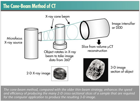
3-D X-ray systems include a computerized tomography (CT) subsystem that combines many 2-D images or cross-
section “slices” to reconstruct a 3-D representation of the sample. Some systems project a thin-beam X-ray through one plane of an object from many different angles (known as the thin-beam method). In more advanced scanners a cone-beam pattern is projected that covers an area detector. The sample is manipulated within the cone beam so that many slices, or a volume, can be scanned at once.
For many inspection applications, 2-D X-ray imaging provides enough information for quality control through a real-time, top-down image of the object being viewed. As previously noted, the sample may be oriented by the manipulator through a virtually infinite number of oblique angles to the X-ray beam. Thus, the term “top-down” orientation refers to an angle normal to the surface of the target feature, which may be deep within the sample and at an oblique angle to the air-edge surface.
The primary advantage of 2-D X-ray in-spection is speed. A typical state-of-the-art 2-D X-ray inspection system can produce 25 to 30 images per second. However, a primary limitation of 2-D systems becomes apparent, for example, when imaging double-sided printed circuit boards. In such instances, the X-rays penetrate circuit components on both sides of the board, so that the resulting image appears to show one layer of components overlaying the other, resulting in difficult analysis. Imaging at a carefully chosen oblique angle can ameliorate this situation, depending on the X-ray system and the complexity of the assembly being inspected.
As a practical matter, in 2-D systems the surface of the target may be positioned in contact with the X-ray emitter or up to 400 mm away. In 3-D systems, the sample can be no closer than 5 mm from the emitter because the sample must be able to rotate relative to the X-ray beam direction and requires some spatial relief.
The most notable advantage of 3-D X-ray inspection is the production of highly intuitive images of complex, multilayered phenomena that users can quickly interpret. As in our real, three-dimensional world, a reconstructed 3-D image provides a complete, walk-around picture of the target area, which users can readily recognize. Solder balls, for instance, on the underside of BGAs can be viewed from all angles, and defects such as insufficient wetting or cracks can be easily identified. Vias in chips and printed circuit boards that may not even be identifiable as throughboard features in a 2-D representation can be quickly recognized and readily evaluated in a 3-D image.
The downside of producing a 3-D image is that the process takes much longer than 2-D imaging--from 15 minutes to two hours. To create a 3-D image, numerous, positionally precise informational layers must first be obtained that capture the exposure pattern of the X-rays penetrating the sample at numerous orientations--on the order of 150 to 200 positions, each taken at a slightly different but precisely determined orientation relative to the X-ray emitter.
The CT system then combines all of the images to produce a 3-D reconstruction of the original. About one hour is required to initially set up the sample and calibrate the system. X-ray exposure time may require only minutes; computer processing, another half-hour. As a result, generating the first 3-D image of a sample is a unique, painstaking process that may take as long as one to two hours. However, obtaining subsequent
3-D images that use identical setup parameters may take much less time--as little as 15 minutes.
In the time- and cost-driven context of a lab or fab, the selection of 2-D vs. 3-D imaging is often a tradeoff of factors including time, concomitant expense and a judgment call to determine if the cheaper and faster 2-D mode will suffice, or if the slower but more revelatory 3-D mode is required. The initial decision can be difficult and the requirement for 3-D may not always be discovered--or imposed--until after the inspection procedure starts. As a result, an X-ray inspection system that can toggle between 2-D and 3-D modalities is an ideal solution for many inspection facilities.
One state-of-the-art system, now available from FEINFOCUS, allows the operator to select either a microfocus (down to 1 µm feature recognition), nanofocus (below 0.3 µm feature recognition) or high-power mode (up to 160 KV), depending on the requirements of the application, by simply clicking on a Microsoft Windows-style on-screen icon. The selected mode is available in about five seconds with the images displayed via a different window on the same monitor. The sample remains untouched so that the setup doesn’t have to be recalibrated. The system allows the operator to perform high-resolution 2-D inspection with optimum processing speed, while allowing the user to switch to 3-D for inspection of parts and interconnects that cannot be adequately viewed using 2-D. This on-demand toggling flexibility provides a distinct economy by eliminating the need for having and setting up separate 2-D and 3-D systems.
The savings from an operational cost perspective are even more dramatic. Enabling the operator to switch modes on demand eliminates duplication of the time invested in initially calibrating a setup to obtain the first image in a sample series. In 3-D imaging operations, this can reduce the time to obtain a second image from the approximately two hours required for the initial imaging to only 20 minutes.
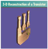 3-D imaging is achieved with a process called axial computerized tomography (ACT) and volume-rendering software. ACT is a reconstruction technology that combines multiple 2-D images of a sample. Each image, or slice, records pixel by pixel the relative transparency or opacity of each feature imaged at a specific orientation to the X-ray source. The ACT process calculates the volume data (voxels) represented by the pixels in each slice relative to the corresponding pixels in every other slice, and assigns the resulting values to a 3-D index according to an underlying algorithm. Each voxel of volume data is processed until a 3-D image of the sample is constructed, such as the transistor shown here. Individual features such as wall thickness or void volume measurements can be obtained directly from the 3-D model due to the known size of the voxel data. 3-D imaging is achieved with a process called axial computerized tomography (ACT) and volume-rendering software. ACT is a reconstruction technology that combines multiple 2-D images of a sample. Each image, or slice, records pixel by pixel the relative transparency or opacity of each feature imaged at a specific orientation to the X-ray source. The ACT process calculates the volume data (voxels) represented by the pixels in each slice relative to the corresponding pixels in every other slice, and assigns the resulting values to a 3-D index according to an underlying algorithm. Each voxel of volume data is processed until a 3-D image of the sample is constructed, such as the transistor shown here. Individual features such as wall thickness or void volume measurements can be obtained directly from the 3-D model due to the known size of the voxel data.
Typically for 3-D inspection, the region of interest of the part or interconnect is first identified and located. Then a multitude of images are taken in a 360-degree circle by rotating the sample, while the X-ray beam is being projected in a cone shape that blankets the entire detector element, as seen in the figure below. The images are subsequently recombined using the software into a 3-D visualization model. Manipulators for a 2-D/3-D X-ray system must enable highly precise movement around as many as six axes. The movement can be automatically controlled by a computer or manually controlled with a joystick.
A combined 2-D/3-D X-ray inspection system greatly facilitates the inspection of complex samples. For example, if a BGA package or a glow plug is being viewed using the 2-D mode and a 3-D image is required to examine for a possible defect, the operator simply punches a key on the keyboard and begins the 3-D operation. As the multiple images are taken in a 360-degree rotation around the part and the 3-D image is constructed by
the software, the operator begins to view the image on a second window on the same monitor. Once viewing is completed, the operator is able to shift back to 2-D and continue the process.
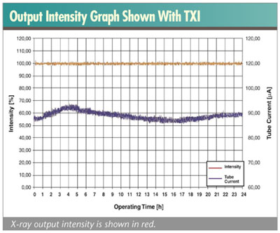
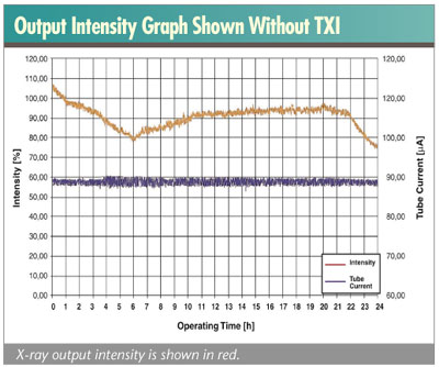
The performance and accuracy of a combined 2-D/3-D X-ray system requires a constant focal spot size and spatial position. True X-ray intensity (TXI) is an innovative control technology developed by FEINFOCUS to provide a controlled and stable output intensity of X-ray emissions based on real-time sampling of the emissions themselves. This control strategy contrasts with older systems that attempt to control the emissions by
controlling the input level of the high voltage and current to the X-ray tube. The new strategy is distinctly more precise, and enables the production of sharp and consistent 2-D images and data that can be reconstructed into an accurate, viable and complete 3-D image. Without precisely controlling the X-ray intensity, the reconstructed 3-D image would be degraded and may be impossible to achieve. The figures on the previous page show output intensity graphs with and without TXI.
Optimum flexibility in X-ray inspection is achieved by combining real-time 2-D imaging with 3-D ACT in one system. Users can switch from one mode to the other with just a keystroke as often as necessary during the inspection process. Having a multimodal capability in one system eliminates the need to purchase independent, free-standing 2-D and 3-D systems, yielding significant savings in capital and operational costs.
Guido Rademaker, Ph.D., is an application engineer with FEINFOCUS (Garbsen, Germany), specializing in µCT X-ray. Prior to joining FEINFOCUS, Rademaker worked in the radiology department of the German Cancer Research Center, concentrating on CT and MRI physics and medicine. He holds a Ph.D. in physics, with further training in radiation protection. He can be reached at g.rademaker@FEINFOCUS.com.
|
 Components of X-ray inspection systems